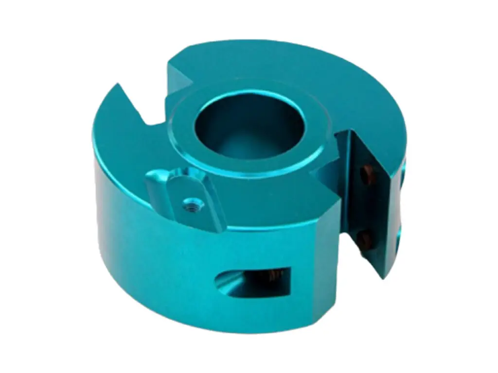


CNC Machined Aluminum Slotted Drive Hub
Slotted drive hubs machined from 6061-T6, with a H7 bore round to 0.02 mm, three drive slots indexed within 0.05 mm, a JS9 keyway and dynamic balance to G6.3 at 3,000 rpm. Anodized with the bore masked so the fit is unchanged.
- Bore H7, Roundness 0.02 mm
- Slots Indexed Within 0.05 mm
- Keyway Cut to JS9
- Balanced to G6.3
*Send the mating coupling spider and the shaft tolerance. A slot cut 0.05 mm wide will load one dog first, and that dog fails long before the others show wear.
Slotted Drive Hub Overview
A slotted hub is a torque part: the slots have to be equally spaced, the bore has to be concentric with the flange and the keyway has to be on the same axis, or the coupling runs out and the spider wears on one side.
The hub is turned complete, including the bore and flange, then moved to the mill where the slots are cut with the bore used as the rotary datum before the keyway is broached from the same bore.
6061-T6 Aluminium Bar
6061-T6 is used for the flange stiffness at the slot roots and because it machines to a clean H7 bore. It is the default for servo couplings up to 30 Nm.
7075-T6 or 6082-T6
7075 is chosen where the slots carry a reversing load and the root has to resist fatigue, and 6082 where the hub is welded to a tube or a pulley body.
For a hub above 120 mm diameter, the blank is turned from plate rather than bar, because a bar that size carries more internal stress and will move after the slots are cut.
Slotted Drive Hub Specifications
Turning, milling and slotting data for drive hubs, with the bore, slot and balance values that decide whether the coupling runs quiet.
| Specification | Machining Data | Specification | Machining Data |
|---|---|---|---|
| Product | Slotted Drive Hub / Coupling Hub | Machining Process | CNC Turning, Milling, Slotting |
| Material | 6061-T6 Aluminium Bar | Envelope | Ø 50 – 180 mm |
| Bore | Ø 15 – 60 mm, H7, Roundness 0.02 mm | Bore to Flange | Square 0.02 mm |
| Drive Slots | 3 – 6 Slots, Width ±0.03 mm | Slot Index | ±0.05 mm, Equal Spacing |
| Keyway | Width JS9, Depth ±0.1 mm | Flange Thickness | 8 – 25 mm |
| Hub Length | 25 – 90 mm | Concentricity | Flange to Bore 0.02 mm |
| Balance | G6.3 at 3,000 rpm | Surface Finish | Ra 1.6 µm Bore, Ra 3.2 µm Slots |
| Customization | Set Screw Holes, Taper Bore, Second Keyway, Lightening Pockets | Lead Time | 5 – 7 Days Sample, 12 – 16 Days Batch |
| Inspection | Air Gauge Bore, CMM Slot Index, Balance Report | Packing | Bore Plug, Foam Wrap, Boxed |
Key Features of Our Drive Hubs
Slots cut from the bore, keyed and balanced after machining.
Slots Indexed From the Bore
The hub is rotated on the bore for each slot, so the index stays within 0.05 mm and all the drive dogs share the torque from the first turn.
Bore Turned Before Slotting
Boring first and slotting second means the slot load path is referenced to the fit, not to the outside diameter, which is often 0.1 mm off centre.
Keyway Cut After Coating Decision
The keyway is cut to JS9 either before anodizing with a plug fitted, or after coating, so a key never needs to be filed to fit.
Balanced as a Finished Part
The hub is balanced after anodizing with the keyway and slots complete, so the correction is made where the metal actually ended up.
Hub that has to drive without runout?
Surface Finishes for Drive Hubs
The bore and keyway are fits, the slots are wear faces and the flange is visible, so coating has to be applied selectively.
| Finish | Main Purpose | Finish | Main Purpose |
|---|---|---|---|
| Type II Anodizing | Corrosion protection and colour coding | Hard Anodizing | Wear resistance in the slots |
| Masked Bore | Keeps the H7 fit after coating | Bead Blasting | Even matte before dye |
| Laser Marking | Slot position and balance mark | Chromate Conversion | Conductive finish on earthed drives |
| Anodizing Build | 10 – 15 µm, Sealed | Vapour Blasting | Satin finish on the flange face |
| Bore Plug | Fitted During Coating | Keyway Protection | Taped to Keep Coating Out |
| Balance Mark | Single Dot After Balancing | Assembly Oil | Light Film on the Bore |
*Anodizing closes an H7 bore by 20 µm and a keyway by the same on both flanks. Bores and keyways are plugged or cut oversize, and the bore is air gauged again after coating.
Put your CNC milling parts into production today
All information and uploads are secure and confidential.
Trusted for Precision CNC Machined Components
Supporting OEM projects with accurate machining, flexible production, and reliable component quality.
Trusted for Precision CNC Milling.
Machining Process for Drive Hubs
The slots are cut with the bore as the rotary datum, so all three drive dogs take load at the same time instead of one carrying the torque.
01. Coupling and Shaft Review
Check the spider, the shaft tolerance and the torque, then set the slot width and the keyway size from the mating parts.
02. Turn the Hub Complete
Turn the outside, the flange and the bore in one set-up to keep the bore concentric to the flange within 0.02 mm.
03. Cut the Drive Slots
Mount on the bore, index each slot from the same datum and cut to width, checking the index with a pin before unclamping.
04. Cut the Keyway
Broach or mill the keyway to JS9 from the bore axis, then deburr the slot roots by hand because that is where a crack starts.
05. Balance and Anodize
Balance to G6.3, mask the bore and keyway, anodize, then re-gauge the bore and mark the balance position.
Send the shaft drawing and the coupling spider, and we will quote a hub with the slots indexed from the bore and balanced after coating.
Slotted Drive Hub FAQs
0.05 mm between slot centres, cut with the bore as the rotary datum. An index error of 0.1 mm means one dog takes the whole torque for the first few degrees of every reversal.
Yes, any taper from 1:10 to 1:5 with the taper gauged against a plug. Taper bores are cut after the slots so the hub is held on the outside diameter during slotting.
Every hub above 80 mm is balanced to G6.3 at the working speed, after anodizing. Below that the hub is symmetrical enough that balancing adds cost without benefit.
It adds 10 to 15 µm per surface, so the bore is masked with a plug or cut oversize. The bore is air gauged after coating and the reading is recorded on the tag.
JS9 width and ±0.1 mm on depth, cut from the bore axis. A keyway that is off centre by 0.1 mm makes the key rock and frets the shaft.
Yes, one or two set screws at 90° or 120°, drilled and tapped after the keyway so the screw lands on the key rather than beside it.
Other CNC Machined Mechanical Components
Explore additional precision CNC machined components manufactured for OEM applications and customized production needs.
Five-axis milled 316L stainless frame bases with compound-angle lightening windows, wall held to 1.5 mm and mounting faces flat.
Custom CNC machined aluminum gearbox housings with bored bearing seats and a split face.
Custom CNC machined aluminum motor bases and mounting pedestals for servo and spindle motors.
Custom CNC machined and anodized robot mounting brackets in 6061-T6 or 7075-T6.
Custom five-axis CNC milled aluminum impellers for centrifugal fans, blowers and vacuum pumps.
Get high‑quality machined parts in as fast as 4 days with our expanded automated CNC milling!