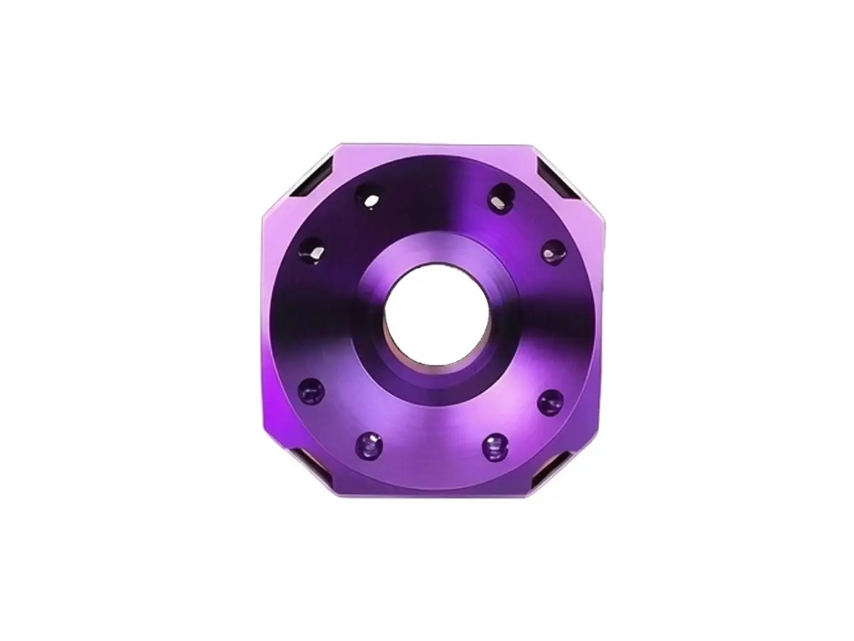
CNC Machined Aluminum Motor Base
Custom CNC machined aluminum motor bases and pedestals for servo motors, spindles and gearboxes. The foot is faced first and the bore is cut from that face, so the motor sits at the correct centre height and the belt runs true without shimming.
- Bore Square to Base 0.02 mm
- Ribbed Underside
- Belt Tension Slots
- Anodized After Machining
*Send the motor frame size and the belt centre distance, because the bore, the slot length and the base height are all set by the drive geometry.
Aluminum Motor Base Overview
A motor base does one thing that is easy to get wrong: it holds a motor at a fixed centre height while a belt pulls sideways on it. If the bore is not square to the foot, the motor sits at an angle and the belt wears on one side.
The base is milled from a solid block with the foot faced first, then the bore is cut and checked square to that face within 0.02 mm. The underside is ribbed so the block can be lighter without losing the stiffness that keeps the belt tension stable.
6061-T6 Aluminum Plate
6061-T6 is the default for brackets and plates that are anodized after machining. It cuts cleanly at high spindle speed, keeps a flat face through thin sections, and takes a uniform dye colour without blotching, which matters when two parts have to match visually.
7075-T6 Aluminum Billet
7075-T6 is used where the part carries load or runs at high cycle rate. Its yield strength is close to mild steel at a third of the weight, so a bracket can be thinner and still hold stiffness. It anodizes to a deeper colour and machines with a better surface, at a higher billet cost.
Height and rib layout are agreed together. A 200 mm tall base in solid section is heavy and still flexes, where a ribbed section at half the weight holds the same centre height.
Aluminum Motor Base Specifications
Machining data for motor bases, agreed against the frame size, the centre height and the belt tension.
| Specification | Machining Data | Specification | Machining Data |
|---|---|---|---|
| Product | Motor Base / Mounting Pedestal | Machining Process | 3-Axis CNC Milling, CNC Boring |
| Material | 6061-T6 / 7075-T6 Aluminum | Typical Tolerance | ±0.03 mm on Bore, ±0.05 mm on Base |
| Base Footprint | 80 × 80 mm to 400 × 300 mm | Squareness | 0.02 mm Bore to Base Face |
| Height | 40 – 250 mm | Flatness | 0.03 mm on the Mounting Foot |
| Bore Diameter | 30 – 150 mm, H7 | Surface Finish | Ra 1.6 µm, Ra 0.8 Bore |
| Features | Ribbed Underside, Belt Slots, Jacking Screws, Dowel Holes | Drawing Format | STEP, STP, IGES, X_T, DWG, DXF, PDF |
| Customization | Height, Bore, Slot Pattern, Colour, Marking | Lead Time | 7 – 12 Days (Prototype), 15 – 22 Days (Batch) |
| Inspection | CMM Squareness, Bore Gauge, Flatness Check | Packing | Base Protected, Foam, Carton |
| Weight Range | 0.5 – 20 kg Finished | Anodizing | Type II 12 – 18 µm |
Key Features of Our CNC Machined Motor Bases
Centre height that stays put when the belt pulls.
Bore Cut After the Foot
The foot is faced first and the bore is bored from that face, so squareness is machined rather than inherited from the block.
Ribbed Underside
Internal ribs carry the belt load without the weight of a solid section, which keeps the base stiff enough that tension does not drift.
Belt Tension Slots
Slot length and position are cut to the adjustment range the drive needs, with the slot walls parallel so the motor slides without cocking.
Jacking Screw Pads
Jacking screw pads are machined flat and tapped so the motor can be lifted off the base for belt changes without a pry bar.
Belt wearing on one side?
Surface Finishes for CNC Machined Motor Bases
A base is usually visible and always load bearing, so the finish is specified on the foot and the bore separately.
| Finish | Main Purpose | Finish | Main Purpose |
|---|---|---|---|
| As Machined | Bare base where it is bolted inside a frame | Type II Anodizing | Corrosion protection and colour on visible bases |
| Bead Blasting | Matte face before dyeing, hides tool marks | Hard Anodizing | Wear resistance on belt tension slots |
| Laser Marking | Centre height and part number on the side face | Masked Bores | Bore left bare to hold the H7 fit |
*Anodizing on the foot changes its thickness by 12 to 18 µm per face. Where the foot has to sit flat on a machined bed, the underside is masked.
Put your CNC milling parts into production today
All information and uploads are secure and confidential.
Trusted for Precision CNC Machined Components
Supporting OEM projects with accurate machining, flexible production, and reliable component quality.
Trusted for Precision CNC Milling.
CNC Machining Process for Aluminum Motor Bases
The bore is machined after the foot is faced, so centre height stays true when the base is bolted down.
01. Drive Geometry Review
Check the motor frame, the centre height and the belt centre distance, and confirm the slot length covers the tension range without overhanging the foot.
02. Facing the Foot
Face the mounting foot and mark it as the datum, since the bore, the slots and the rib depth are all referenced to it.
03. Milling and Boring
Mill the outer profile and the ribs, cut the belt slots, then bore the motor seat and check squareness to the foot before the part is released.
04. Deburring and Anodizing
Break the slot edges, mask the bore and the foot underside where flatness matters, then anodize to the agreed colour.
05. Inspection and Packing
Check squareness, centre height and bore size on a CMM, confirm flatness on a surface plate, and pack with the foot protected.
Have a base that lets the belt walk or the motor tilt? Send the frame size and the belt layout, and we will quote the base that holds centre height.
CNC Machined Aluminum Motor Base FAQs
Centre height sets the belt line. If it is off by 0.2 mm the belt runs at an angle, wears on one edge and loads the motor bearing sideways. Machining the bore after the foot keeps the height within 0.02 mm.
Yes. Slot length and position are set from the drive geometry, and the slot walls are milled parallel so the motor slides without cocking as tension is applied.
A ribbed base typically weighs 35 to 45 percent less than a solid section of the same height, while holding the same stiffness under belt load.
The foot underside is masked when flatness matters, because the coating adds 12 to 18 µm per face and can lift a base off a machined bed at the edges.
The base is machined to the frame size and bore you specify, and assembly can be quoted separately. Most customers fit the motor themselves to control the belt tension.
Seven to twelve days for one base including milling, boring, anodizing and inspection. Repeat orders that reuse the program typically ship in five to seven days.
Other CNC Machined Mechanical Components
Explore additional precision CNC machined components manufactured for OEM applications and customized production needs.
Custom CNC machined aluminium mounting brackets for robots, automation and equipment mounting.
Custom CNC machined aluminium brake booster check valve bodies for motorcycles and automotive systems.
Custom CNC machined aluminum hollow sleeve connectors for robot arm segments and linear modules.
Custom CNC machined robot end effector flanges for tool mounting and automation.
Get high‑quality machined parts in as fast as 4 days with our expanded automated CNC milling!