


Home / CNC-Machining / CNC 5-Axis Machining / Five-Axis CNC Milled Stainless Steel Frame Base
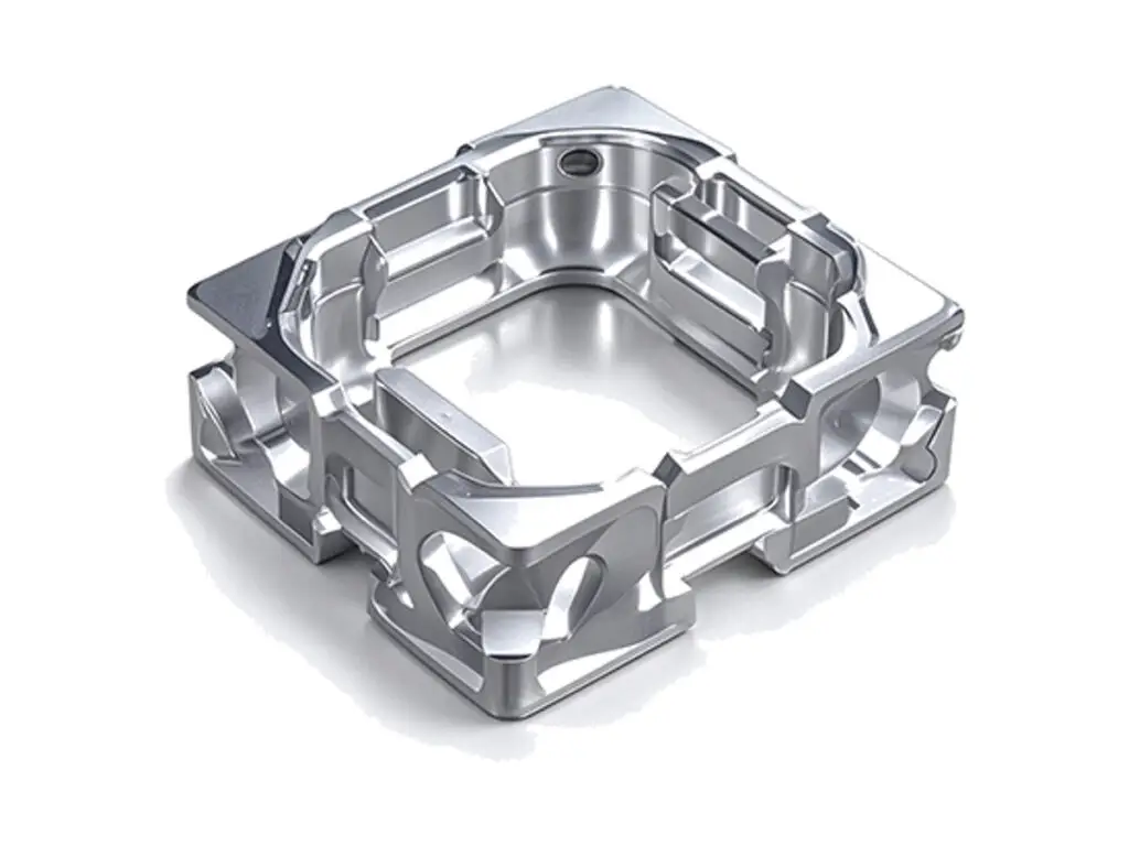
Five-axis milled 316L stainless frame base with compound-angle lightening windows and thin walls

Five-Axis CNC Milled Stainless Steel Frame Base

Five-axis milled 316L stainless frame bases for robot joints, vision modules and lightweight gantries, with compound-angle lightening windows, 1.5 mm walls and mounting faces flat to 0.03 mm. The frame is machined from a solid block in one five-axis set-up, so window walls and mounting faces share a datum.

*Send the mass target and the load path. Removing 60% of the blank is routine, but the wall that carries the load has to stay in the model, and only you know which one that is.

Five-Axis Frame Base Overview

A frame base exists to be stiff and light at the same time, which is a five-axis problem rather than a three-axis one. Windows that run at compound angles remove weight from the corners where it does nothing, but they cannot be cut with a three-axis approach without leaving a stepped wall or a sharp internal corner.

The blank is probed and set on a trunnion, then roughing and finishing run with the tool tilted so the flute engages the wall at a constant angle. That keeps the 1.5 mm wall from chattering, and it lets the window edges meet the mounting face in a radius instead of a burr that would have to be removed by hand.

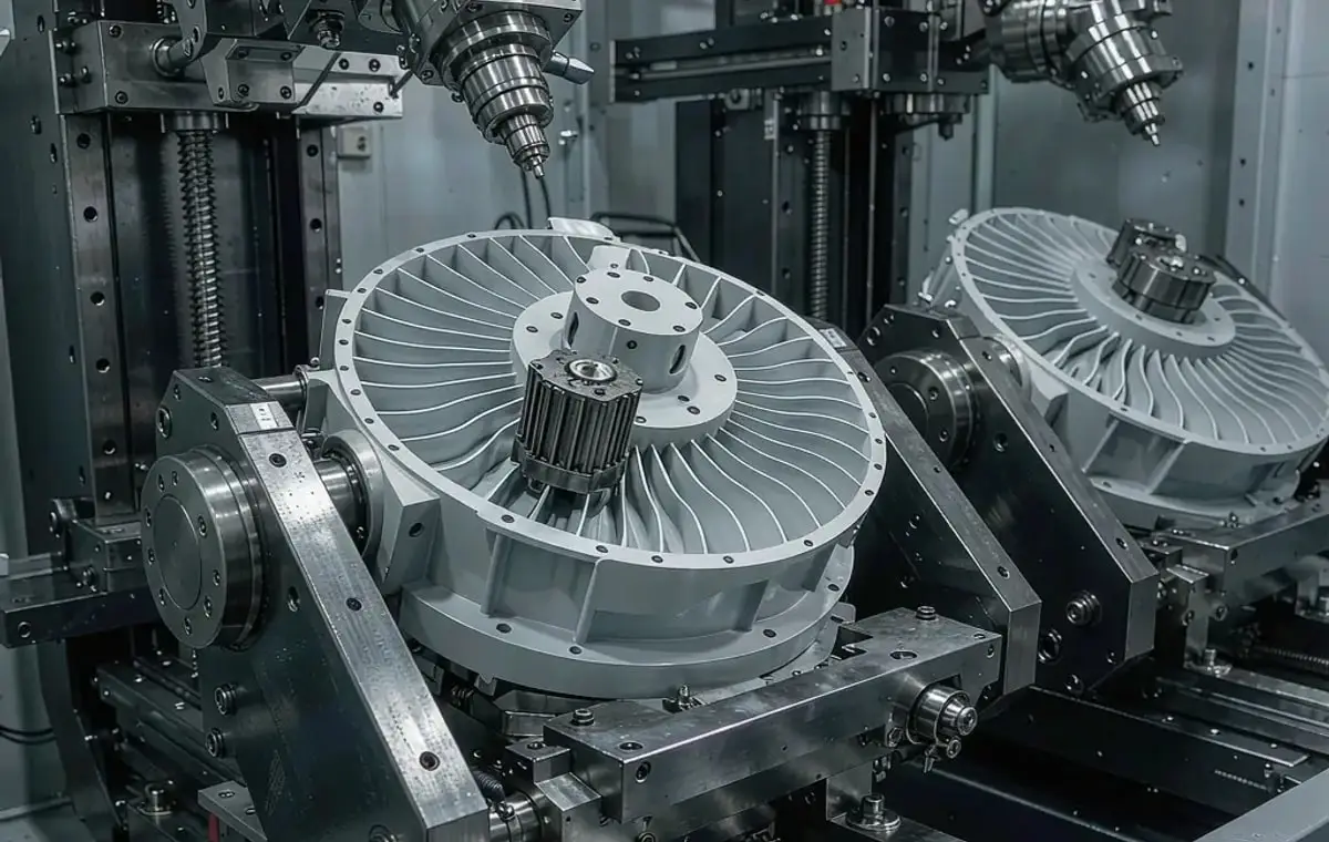
Five-axis machining of a vacuum pump impeller and a twin-body valve housing
304L stainless steel round bar stock for CNC machining

316L Stainless Block

316L is specified for frames that see washdown or corrosive mist, and its work-hardening behaviour is manageable on a five-axis machine where the cut is continuous. It is heavy, which is why so much of the blank is removed.

304L stainless steel plate and block stock for CNC machining

7075-T6 Aluminium for Weight

7075-T6 is the alternative when the frame has to be light rather than corrosion resistant. At a third of the density it removes the same stiffness problem with far less machining time, but it needs anodizing and does not tolerate chlorides.

The material choice is a weight-and-environment trade. A stainless frame is chosen for washdown or magnetic reasons, an aluminium frame for inertia; both are machined the same five-axis way.

Five-Axis Frame Base Specifications

Five-axis machining data for stainless frame bases, with the wall, window and flatness values that decide stiffness after lightening.

SpecificationMachining DataSpecificationMachining Data
ProductLightweight Frame Base for Robot and Vision ModulesMachining Process5-Axis Simultaneous CNC Milling
Material316L Stainless Steel BlockProfile Tolerance±0.03 mm on Window Edges
Envelope60 × 60 × 40 mm to 260 × 200 × 120 mmWall Thickness1.5 – 3 mm, Held ±0.1 mm
Window GeometryCompound Angles 15° – 75°, Radiused Internal CornersMounting Face Flatness0.03 mm Across 150 mm
Mounting HolesM3 to M8, Counterbored or Tapped, Both SidesHole Position±0.02 mm From Datum
Maximum Part Weight RemovedUp to 62% of the blankSurface FinishRa 1.6 µm Faces, Ra 3.2 µm Window Walls
AccessFive-Axis Reach to All Faces Without Re-ClampingPassivationASTM A967 Citric After Machining
CustomizationWindow Pattern, Angle Set, Boss Position, MarkingLead Time10 – 12 Days (Prototype), 16 – 20 Days (Batch)
InspectionCMM Scan vs Model, Wall Ultrasonic Check, FlatnessPackingFoam Cradle, Bagged, Crated

Key Features of Our Five-Axis Frame Bases

Lightened where the load does not run, left solid where it does.

Compound-Angle Windows

Windows are cut with the tool tilted on two axes, so the wall meets the face at a constant thickness and the frame loses weight without a stress-raising sharp corner.

1.5 mm Walls Without Chatter

Thin walls are finished with a constant engagement strategy and a support rib left in until the last pass, which keeps the wall from springing away from the cutter.

All Faces in One Set-Up

Mounting faces, dowel bores and window walls are cut without re-clamping, so the frame does not pick up the 0.02 to 0.05 mm shift that a second set-up introduces.

Scanned Against the Model

The finished frame is scanned on a CMM and compared with the CAD model, so wall thickness and window position are reported rather than assumed.

Have a frame that needs to lose half its weight?

Surface Finishes for Stainless Frame Bases

Heavy stock removal leaves a machined surface that needs passivation before it will resist corrosion, so the finish step is part of the process.

FinishMain PurposeFinishMain Purpose
PassivationRestores corrosion resistance on 316L after heavy stock removalElectropolishingBright window walls on visible frames
Glass Bead BlastingEven matte face that hides the five-axis tool pathVibratory FinishingRounds window edges before passivation
Laser MarkingModule ID and axis datum marks on the frameMasked PassivationKeeps dowel bores bare for press fits

*Electropolishing removes 5 to 10 µm and slightly opens dowel bores. Frames with press-fit dowels are masked at the bore or the bore is finished after polishing.

logo

Put your CNC milling parts into production today

All information and uploads are secure and confidential.

Trusted for Precision CNC Machined Components

Supporting OEM projects with accurate machining, flexible production, and reliable component quality.

Mechanical Equipment Customer
The compound-angle pads were right first time, so the frame did not need shimming at assembly.

Industrial Components Buyer
Thin walls stayed straight through machining, and the base did not ring when the machine moves.

Equipment Manufacturer
Windows came out without tool marks on the inside faces, which we normally have to polish out.

OEM Customer
OEM Customer
The datum scheme they proposed meant our inspection matched theirs line for line.

Automation Industry Customer
The customized machining solution provided the dimensional accuracy required for our rotating equipment components.
Trusted for Precision CNC Milling.

Five-Axis Machining Process for Frame Bases

Compound-angle windows are cut with the tool tilted, so the frame loses weight without gaining a single sharp internal corner.

01. Load Path and Mass Review

Check the model for walls below 1.5 mm, sharp internal corners and windows that cut the load path, and agree a mass target before any material is removed.

02. Blank Prep and Probing

Square the block, face the datum, then probe it on the trunnion so the five-axis program is referenced to the real blank rather than to a nominal size.

03. Rough and Finish Windows

Rough the windows with a stepped tool path, then finish with the tool tilted so the wall is cut at constant engagement and the floor blends into the face with a radius.

04. Faces, Bores and Passivation

Face the mounting surfaces, bore and tap the holes in the same set-up, then passivate the frame to restore the oxide layer on the machined walls.

05. Scan, Weigh and Pack

Scan the frame against the model, record the finished mass, check flatness on the mounting face, then pack in a foam cradle so the thin walls are not loaded in transit.

Send the frame model with the mass target and the mounting interface, and we will come back with a lightening pattern and a machining plan.

Five-Axis Frame Base FAQs

Between 45% and 62% on a typical robot or vision frame, depending on how much of the outer skin has to stay for mounting. Going beyond that usually means the walls are too thin to hold a thread or a dowel.

Because the window walls run at compound angles. A three-axis machine can only cut them with a stepped wall or a re-clamp, and both show up as a thickness variation that reduces stiffness exactly where the frame is loaded.

Yes, with a support rib left in place until the final pass and a constant-engagement finishing path. After machining, the wall is checked by ultrasonic thickness at six points per window.

0.03 mm across 150 mm, measured after passivation rather than before, because stress release during machining can move the face by a few hundredths.

Yes, if you send the interface drawing. Dowel bores and bolt patterns are cut from that datum in the same set-up as the windows, so the frame lands on the interface without shimming.

Ten to twelve days for a prototype including programming, five-axis machining, passivation and CMM scanning. Repeat batches run sixteen to twenty days depending on wall thickness and inspection scope.

Other CNC Machined Mechanical Components

Explore additional precision CNC machined components manufactured for OEM applications and customized production needs.

Custom CNC machined aluminum automotive housings for sensor, actuator and pump assemblies.

Precision CNC machined aluminum indexing rotary tables for automation cells.

Precision CNC machined aluminum connecting plates for robot modules and automation equipment.

Custom CNC machined aluminium drone components, including arm mounts, motor mounts and frame fittings.

Custom CNC machined aluminium filament stand brackets for 3D printer spool holders.

Get high‑quality machined parts in as fast as 4 days with our expanded automated CNC milling!

Scroll to Top