

Home / CNC-Machining / CNC Milling / Five-Axis CNC Milled Aluminum Impeller
Five-axis CNC milled aluminum impeller for a centrifugal fan

Five-Axis CNC Milled Aluminum Impeller

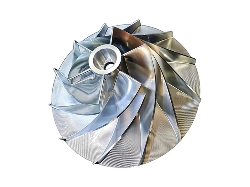
Custom five-axis CNC milled aluminum impellers for centrifugal fans, blowers and vacuum pumps, cut from a single billet so the blade surfaces, hub bore and backplate stay in one datum instead of being assembled from separate parts.

*Send the flow rate, duty speed and hub interface before the blade profile is finalized, as all three decide the trim diameter and the balance grade.

Aluminum Impeller Overview

Five-axis milled impellers for fans, blowers and pumps, where airflow, balance and bore fit decide whether the assembly runs quietly.

An impeller converts shaft power into flow, and every one of its surfaces does a job: the blade profile sets the head and efficiency, the hub bore sets the running fit, and the backplate sets the axial clearance to the housing. Milling all three from one billet keeps them in a single datum, which is why a machined impeller usually needs less trim balance than a welded or cast one.

The difficulty is not the shape but the stiffness. Blades are thin, unsupported at the tip and interrupted by the flow channel, so a three-axis tool path pushes them away from the cutter and leaves a profile that is right in the file and wrong on the part. Five-axis simultaneous milling keeps the tool normal to the blade surface, shortens the overhang and lets the root fillet be cut in the same pass, which is the difference between a part that balances first time and one that needs correction.

SINORISE machines impellers from Ø60 to Ø400 mm with 6 to 24 blades, open or shrouded, in 6061-T6, 7075-T6 and 2024-T351. Prototypes and small batches are the normal case, including re-trimming an existing impeller to a smaller diameter, reproducing a worn impeller from a scan, and machining a hub interface to match a new motor shaft.

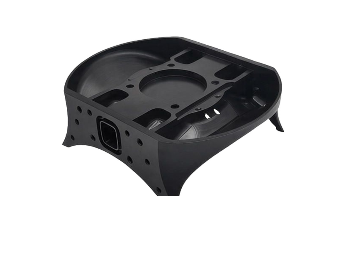
CNC milling of a lightening hole cover plate, a pneumatic manifold block and a sensor enclosure
6061-T6 aluminium round bar stock for CNC turning

6061-T6 Aluminum

6061-T6 is the default for general ventilation and process fans. It machines cleanly at high spindle speeds, holds a thin blade without cracking, anodizes to an even colour and is the least expensive of the three grades, which matters on impellers that are large in diameter but simple in blade form.

Its limit is strength at speed. Above roughly 6,000 rpm the blade root starts to carry more load than the temper comfortably allows, and the tip growth that follows changes the clearance to the housing.

7075-T6 aluminium round disc blank for CNC machining

7075-T6 Aluminum

7075-T6 is specified for high-speed fans, vacuum pump rotors and competition parts where blade stiffness decides the result. Its strength is close to that of mild steel at a third of the weight, so blades can be thinner and the hub smaller for the same flow.

It is less forgiving to machine: the material is harder on cutters, it cannot be welded, and thin sections need light radial cuts to avoid chatter. Anodizing also shows alloying streaks, so cosmetic parts are usually bead blasted before coating.

Grade, trim diameter and balance grade should be specified together, since each changes the blade thickness and the hub geometry.

Aluminum Impeller Specifications

Machining and balance data for five-axis milled impellers, agreed to the fan duty and the motor interface.

SpecificationMachining DataSpecificationMachining Data
ProductAluminum Impeller / Blower WheelBlade MachiningFive-Axis Simultaneous Milling, Flow Channels to CAD Surface
Material6061-T6 / 7075-T6 / 2024-T351Hub MachiningTurning, Boring, Broaching, Keyway Cutting
Machining Process5-Axis CNC Milling, CNC Turning, DrillingSurface FinishRa 1.6 \\\\µm on Flow Surfaces, Ra 0.8 on Bore
Typical Tolerance\\\\±0.02 mm on Blade ProfileBalance GradeG6.3 at 3,000 rpm (G2.5 on Request)
Diameter Range\\\\Ø60 \\\\– \\\\Ø400 mmBore FitH7 / H8, Concentricity 0.01 mm
Blade Count6 \\\\– 24 Blades, Backward or Forward CurvedWall ThicknessMinimum 1.5 mm at Blade Tip
Machined FeaturesBlades, Hub Bore, Keyway, Backplate, Balance HolesDrawing FormatSTEP, STP, IGES, X_T, DWG, DXF, PDF
CustomizationBlade Angle, Hub Interface, Trim Diameter, CoatingLead Time7\\\\–12 Days (Prototype), 12\\\\–20 Days (Batch)
InspectionCMM Blade Scan, Bore Gauge, Balance ReportPackingFoam-Cradled, Individually Boxed, Carton

Key Features of Our CNC Milled Impellers

Built for airflow, balance and a bore that fits the shaft without shimming.

Blade Surface Machining

Blades are milled with the tool kept normal to the surface, so the profile follows the CAD model from leading edge to trailing edge and the root fillet is cut in the same pass instead of being blended by hand.

Hub and Bore Accuracy

The hub bore is turned and bored after the blades are cut, to H7 with 0.01 mm concentricity to the blade datum, so the impeller runs true on the shaft without a balancing correction for eccentricity.

Thin-Wall Control

Blade thickness is held by taking light radial cuts at high spindle speed and supporting the blade from behind where the geometry allows, which keeps tip deflection and chatter marks out of the finished surface.

Balancing and Inspection

Each impeller is balanced to G6.3 or G2.5 at the service speed, then scanned on a CMM against the blade model, with both reports issued with the part.

Need an impeller that balances first time?

Surface Finishes for CNC Machined Impellers

Finishing on an impeller is about airflow as much as protection, so the flow surfaces and the bore are usually treated differently.

FinishMain PurposeFinishMain Purpose
As MachinedBare milled surface where airflow and cost governAnodizingCorrosion protection and colour identification
Bead BlastingUniform matte flow surface, removes tool marksHard AnodizingWear resistance on hub and bore faces
PolishingRa 0.8 flow channels for reduced dragBalancingMaterial removal or set screws to reach the balance grade

*Flow-surface finish, coating thickness and balance grade interact: a coating applied after balancing shifts the balance, so the sequence is agreed before production.

logo

Put your CNC milling parts into production today

All information and uploads are secure and confidential.

Trusted for Precision CNC Machined Components

Supporting OEM projects with accurate machining, flexible production, and reliable component quality.

Mechanical Equipment Customer
The impeller balanced to grade without any correction on our side, and the blade finish matched the sample we approved.

Industrial Components Buyer
Five-axis programming was handled by them, which saved us from rebuilding the blade surfaces ourselves.

Equipment Manufacturer
The bore fitted the motor shaft first time, and the runout was inside what our fan housing allows.

OEM Customer
OEM Customer
Prototype lead time was shorter than our previous supplier, and the CMM report came with the parts.

Automation Industry Customer
The customized machining solution provided the dimensional accuracy required for our rotating equipment components.
Trusted for Precision CNC Milling.

CNC Machining Process for Aluminum Impellers

From blade model to balance report, each impeller follows one controlled route so the profile, the bore and the balance are all measured against the same datum.

01. Blade Model Review

Check the blade surfaces for tangency, minimum tip thickness and root fillet radius, then confirm the hub interface and the trim diameter against the fan duty.Thin or undercut blade tips are corrected in the model before programming, not on the machine.

02. Billet Preparation

Select 6061-T6 or 7075-T6 billet with enough stock for the backplate and hub, face both ends parallel, and mark the datum face that all five-axis operations are programmed from.

03. Five-Axis Milling

Rough the flow channels with a bull-nose cutter, semi-finish the blade flanks, then finish with a ball-nose cutter kept normal to the surface. The hub, backplate and balance pads are machined in the same setup to keep the datum intact.

04. Balancing and Finishing

Balance the impeller at the service speed and correct on the balance pads, then apply the specified coating or polish. When both are required, balancing is repeated after coating to confirm the grade still holds.

05. Inspection and Report

Scan the blades on a CMM against the model, gauge the bore and keyway, and check the backplate runout. The dimensional report and the balance report are issued with the parts.

Have an impeller that needs re-trimming or a new blade profile? Send the model, the duty point and the shaft interface to start the review.

CNC Machining Milling Aluminum Impeller FAQs

Yes. A STEP or X_T file with the blade surfaces and hub interface is enough to quote and program. If the model is a scan of an existing impeller, we rebuild the blade surfaces into a machinable solid and send it back for approval before cutting.

Blades down to 1.5 mm at the tip are practical in 7075-T6. Below that the blade deflects under cutting load and the profile drifts, so the part is usually split into a milled hub and a formed or welded blade set instead.

Yes. Impellers are balanced to G6.3 at the service speed as standard, and to G2.5 when the drawing calls for it. Unbalance is corrected by removing material from the balance pads or, on closed wheels, by adding set screws in the hub.

7075-T6 is the usual choice above roughly 6,000 rpm because its higher strength keeps the blade tips from growing under centrifugal load. 6061-T6 is adequate for lower speeds, humid air streams and parts that need a uniform anodized finish.

Yes. Keyways are broached or milled, splines are cut on a fourth axis, and clamping hubs with a split and pinch bolt are machined as one piece. The bore is finished after the blades so the blade load does not distort the fit.

A single impeller is typically 7–12 days including five-axis programming, machining, balancing and inspection. Small batches of 5–50 pieces run 12–20 days depending on material and coating.

Other CNC Machined Mechanical Components

Explore additional precision CNC machined components manufactured for OEM applications and customized production needs.

Custom CNC machined aluminium housings for automation and electronic equipment.

Custom CNC machined hardened steel sleeves for robotic joints and motion assemblies.

Custom CNC machined aluminum hollow sleeve connectors for robot arm segments and linear modules.

Custom CNC machined aluminium cavity bases for automation and electronic equipment.

Custom CNC machined aluminium motorcycle components, including clamps, covers, mounts and bearing housings.

Get high‑quality machined parts in as fast as 4 days with our expanded automated CNC milling!

Scroll to Top