


Home / CNC-Machining / CNC Milling / Custom CNC Machined Aluminum Cavity Base
cavity base main v2

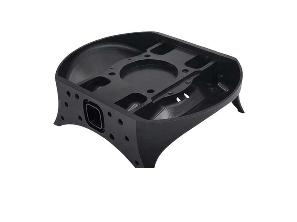
Custom CNC Machined Aluminum Cavity Base

Custom CNC machined aluminium cavity bases for automation equipment, sensor housings and lightweight structural assemblies, machined as one part with the mounting face, cavity and fixing holes held to the drawing.

*Send your 3D model and the required wall thickness to confirm feasibility before machining.

Aluminum Cavity Base Overview

A cavity base carries two jobs at once: it locates the assembly on the machine frame, and it forms the pocket that protects or houses the components inside. Both functions are machined into the same block, so the relationship between the mounting face and the cavity walls decides how the finished unit fits.

These bases are machined from solid aluminium rather than cast or fabricated, which suits low and medium volumes, design changes between builds, and pockets with thin walls or sharp internal corners that a casting would need draft angles to release.

The main machining risks are wall deflection and heat build-up. Pockets are roughed in stages, walls are supported during finishing, and thin sections are checked before the final face is cut so the base stays flat after the cavity is opened.

SINORISE machines cavity bases from customer STEP files, including black anodised versions for optical and inspection equipment, and versions with cable openings, sensor windows and mounting bosses added in the same setup.

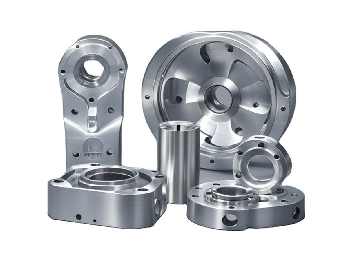
Anodizing of a flanged manifold housing and a cylinder head deck plate
6061-T6 aluminium flat plate stock for CNC milling

6061 Aluminum

6061-T6 is the usual choice for cavity bases: it machines cleanly, holds a stable cavity shape after stress relief, and anodises evenly, including inside pockets where finish coverage matters for cleaning and appearance.

7075-T6 aluminium billet block stock for CNC milling

7075 Aluminum

7075-T6 is used where the base carries load or where walls must stay thin under vibration. It machines to a sharper edge and higher strength, but anodising builds less colour uniformity, so cosmetic requirements should be agreed first.

Wall thickness, pocket depth and finish should be reviewed together with the drawing before machining.

Aluminum Cavity Base Specifications

Key machining data for cavity bases, with tolerances and finishes agreed to the drawing.

SpecificationMachining DataSpecificationMachining Data
ProductAluminum Cavity BaseCavity MachiningRoughing, Semi-Finishing, Finishing, Corner Relief
Material6061-T6 / 7075-T6 AluminumWall Thickness1.5–5 mm (Typical)
Machining ProcessCNC Milling, 3/4/5-Axis MachiningSurface FinishBlack Anodizing, Anodizing, Bead Blasting, As Machined
Typical Tolerance±0.02–±0.05 mmInspectionCMM, 2.5D Measuring System, Wall Thickness Gauge
Flatness0.05 mm per 300 mmProductionPrototype, Small Batch, Medium Batch
Machined FeaturesPocket, Mounting Face, Fixing Holes, Cable Opening, BossesDrawing FormatSTEP, STP, IGES, DWG, DXF, PDF
Max Part Size800 × 500 × 200 mmLead Time5–10 Days (Prototype), 10–18 Days (Batch)
CustomizationMaterial, Wall Thickness, Pocket Layout, Finish, MarkingPackingFoam Separated, Carton, Pallet

Key Features of Our Aluminum Cavity Bases

Cavity work is judged by what happens after the pocket is opened, so the process is built around keeping the base flat and the walls even.

Cavity and Face in One Setup

The mounting face, cavity opening and fixing holes are machined in a single clamping, so the pocket sits square to the face that locates the assembly.

Controlled Wall Thickness

Pockets are roughed with support material left in place and finished in light passes, which keeps thin walls from springing and holds the nominal thickness across the part.

Flat Base After Machining

Material is removed symmetrically where the design allows, and the base is checked on a surface plate after the cavity is cut rather than only after the outside profile.

Finish Inside the Pocket

Anodising coverage inside the cavity is controlled by rack position and drainage, so the pocket is protected and cleanable rather than only the visible outer faces.

Need a Cavity Base for Your Enclosure or Fixture?

Surface Finishes for Aluminum Cavity Bases

Finish selection for a cavity base usually follows the environment inside the pocket as much as the outside appearance.

FinishMain PurposeFinishMain Purpose
AnodizingCorrosion protection and colour coding for part identificationPowder CoatingProtective coating for non-critical covers and guards
Bead BlastingUniform matte texture before anodizingPassivationRemoves machining residue before assembly
Hard AnodizingWear resistance on locating and clamping facesAs MachinedNatural machined surface where no coating is needed

*Hard anodizing changes pocket dimensions slightly; where fits are specified inside the cavity, masking or post-finish sizing should be agreed.

logo

Put your CNC milling parts into production today

All information and uploads are secure and confidential.

Trusted for Precision CNC Machined Components

Supporting OEM projects with accurate machining, flexible production, and reliable component quality.

Mechanical Equipment Customer
The cavity base samples matched our design requirements accurately, and the machining quality was consistent throughout the prototype stage.

Industrial Components Buyer
The engineering support helped us optimize the design before production, reducing potential machining issues.

Equipment Manufacturer
The CNC machined cavity bases achieved the required fit and surface quality for our assembly application.

OEM Customer
OEM Customer
The production process was smooth from prototype validation to small batch manufacturing, with good communication and delivery performance.

Automation Industry Customer
The customized machining solution provided the dimensional accuracy required for our rotating equipment components.
Trusted for Precision CNC Milling.

CNC Machining Process for Aluminum Cavity Bases

A cavity base is mostly a sequence problem: remove material without moving the faces that matter.

01. Drawing and Wall Review

Check wall thickness, pocket depth, corner radii and the finish callout before quoting, and flag any section that needs support during machining.

02. Blank Preparation and Stress Relief

Cut the blank oversize and stress relieve it so the pocket does not distort when the outer profile is later machined.

03. Roughing the Cavity

Remove the bulk of the pocket material in stepped passes, leaving even allowance on walls and floor.

04. Finishing Faces and Walls

Finish the mounting face and cavity walls in light cuts, then drill, tap and ream the fixing holes relative to the finished face.

05. Inspection and Finishing

Check flatness, wall thickness and hole position on a CMM, deburr the pocket edges, then anodise and pack.

Have a cavity base drawing with thin walls or tight pocket tolerances? Send the STEP file and quantity to receive a machining review and quote.

Aluminum Cavity Base CNC Machining FAQs

Walls of 1.5 mm are practical in 6061 for shallow pockets, and 2–3 mm is common for deeper cavities. The limit depends on pocket depth, corner radius and whether the wall is supported at the bottom, so the drawing is reviewed before machining rather than after.

Flatness is controlled by stress relieving the blank, removing material evenly and finishing the mounting face after the cavity is roughed. Typical result is 0.05 mm per 300 mm, with tighter values available when the drawing requires them.

Yes. Openings, windows and mounting bosses are machined in the same setup as the cavity wherever the geometry allows, which keeps their position relative to the mounting face and avoids a second operation.

Black anodising is usual because it reduces stray reflection inside the cavity. Where the base also needs wear resistance at locating faces, hard anodising can be applied with the cavity masked.

Prototypes are usually 5–10 days after drawing approval, and batches 10–18 days depending on pocket depth, finish and inspection requirements.

Yes. Wall thickness is measured at agreed points, and the report is issued with the flatness and hole position results so the cavity can be verified against the drawing on arrival.

Other CNC Machined Mechanical Components

Explore additional precision CNC machined components manufactured for OEM applications and customized production needs.

Custom CNC machined aluminium motorcycle components, including clamps, covers, mounts and bearing housings.

Custom CNC machined robot end effector flanges for tool mounting and automation.

Custom CNC machined aluminium link brackets for automation linkages and robot assemblies.

Custom CNC machined stainless steel multi jaw clamping plates for lathe, grinder and wheel hub fixtures.

Custom CNC machined aluminium fuel pump blocks for automotive and motorsport fuel systems.

Get high‑quality machined parts in as fast as 4 days with our expanded automated CNC milling!

Scroll to Top