

Home / CNC-Machining / CNC Milling / CNC Machined Aluminum Pneumatic Manifold Block
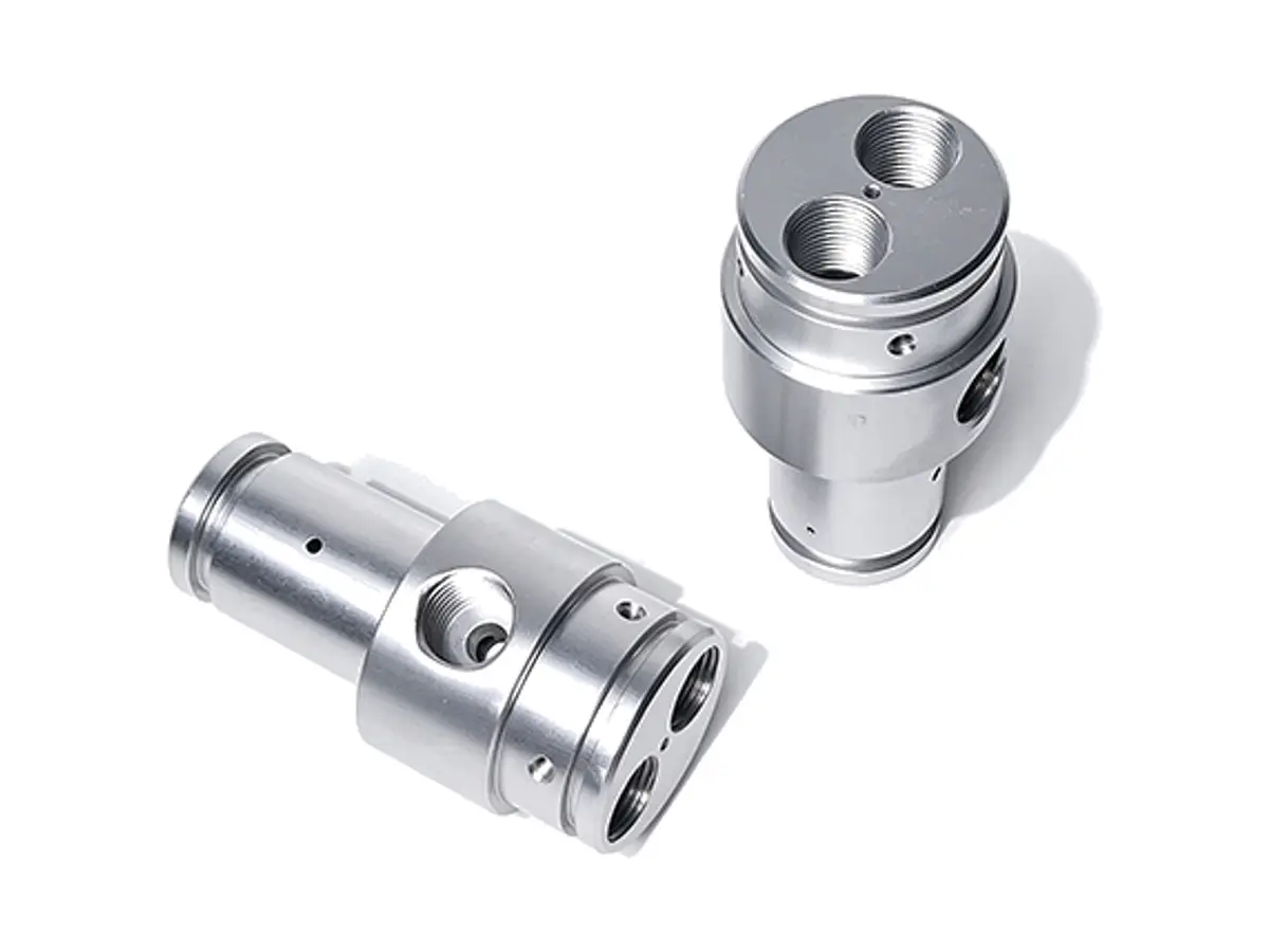
CNC machined anodized aluminum pneumatic manifold block with six tube ports on one pitch

CNC Machined Aluminum Pneumatic Manifold Block

Pneumatic manifold blocks machined from 6061-T6, with six G1/8 ports on a 20 mm pitch held to ±0.05 mm, a Ø8 cross-drilled gallery straight to 0.05 mm, sealing faces flat to 0.05 mm and a pressure decay test at 1.0 MPa before anodizing.

*Send the valve stack drawing and the tube routing. The port pitch is set by the fittings you already use, and a manifold that is 0.2 mm out on pitch will cross-thread a push-in fitting every time.

Pneumatic Manifold Block Overview

A manifold block is judged by two things: whether every fitting threads in by hand, and whether the gallery is clean enough that the valve does not breathe air past a seal. Both come from the order the holes are cut in.

The block is squared first, the port face is machined as the datum, then the ports are drilled and tapped, the gallery is cross-drilled from both ends and the block is flushed and pressure tested before the anodizing line.

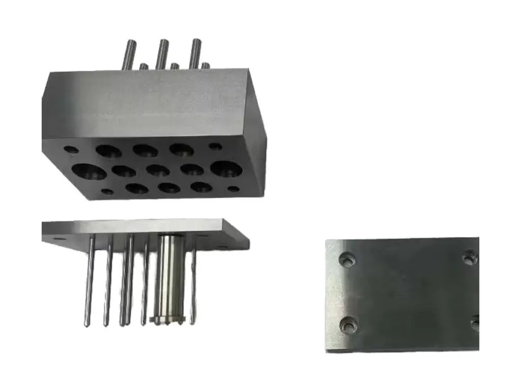
CNC milling of a lightening hole cover plate, a pneumatic manifold block and a sensor enclosure
6061-T6 aluminium flat plate stock for CNC milling

6061-T6 Aluminium Block

6061-T6 is used because the gallery is cross-drilled through a 50 mm section and the block still has to hold thread torque at every port. It also anodizes without closing the G1/8 threads if they are masked.

7075-T6 aluminium billet block stock for CNC milling

6082-T6 or 7075-T6

6082-T6 is specified when the block carries the valve stack as a structural member, and 7075-T6 when the ports are close together and the wall between them drops under 4 mm.

Below a 4 mm wall between ports the block distorts when the fittings are tightened; the fix is more aluminium, not a harder alloy.

Pneumatic Manifold Block Specifications

Milling and drilling data for air distribution blocks, with the port, gallery and leak values that decide whether the stack runs dry.

SpecificationMachining DataSpecificationMachining Data
ProductPneumatic Manifold Block / Air Distribution BlockMachining Process3-Axis CNC Milling, Cross Drilling, Tapping
Material6061-T6 Aluminium BlockEnvelopeUp to 220 × 120 × 70 mm
Port Pitch20 mm, ±0.05 mmPort ThreadG1/8 to G1/2, Class 6H
Gallery BoreØ 6 – 12 mm, Straightness 0.05 mmGallery DepthCross-Drilled from Both Ends, Plugs Fitted
Port FaceFlat 0.05 mm, Square to the GalleryLeak Test1.0 MPa Air, 60 s, No Drop
SurfaceRa 1.6 µm on the Sealing FacesBlock Squareness0.05 mm per 100 mm
Port Count2 – 12 Ports, Any ArrangementMounting HolesØ 6.6 mm Through, ±0.10 mm
CustomizationPort Count, Tube Stubs, Mounting Flange, Name PlateLead Time4 – 6 Days Sample, 10 – 14 Days Batch
InspectionCMM Port Pitch, Thread Gauges, Pressure Decay TestPackingPort Caps, Foam Wrap, Individually Boxed

Key Features of Our Manifold Blocks

Ports and gallery from one set-up, flushed and pressure tested before coating.

Ports on One Machined Pitch

All ports are drilled from the same datum face in a single programme, so the pitch stays within 0.05 mm and a fitting starts by hand at every station.

Gallery Cross-Drilled From Both Ends

The bore is drilled from each end and met in the middle, which keeps it straight to 0.05 mm and lets the swarf out instead of packing it into a blind corner.

Threads Cut to a Pre-Plate Size

Threads are tapped to allow for the 8 µm anodizing build and checked with a Go/No-Go gauge after coating, so a fitting does not need a tap to seat.

Pressure Decay Test Before Packing

Every block is plugged, charged to 1.0 MPa and watched for 60 s; a block that drops pressure is stripped and re-drilled, not shipped and hoped for.

Manifold that has to seal at every port?

Surface Finishes for Manifold Blocks

The outside is cosmetic, the threads and the sealing faces are functional, and the two cannot be treated the same way.

FinishMain PurposeFinishMain Purpose
Black AnodizingCorrosion protection on the visible blockClear AnodizingKeeps threads easy to inspect
Masked ThreadsThreads stay at gauge size after coatingBead BlastingEven matte before dye
Laser MarkingPort numbers and flow directionChromate ConversionConductive finish for earthed machines
Anodizing Build8 – 12 µm, SealedUltrasonic CleanBefore and after tapping
Port CapsFitted After Coating and GaugingVapour BlastingSatin finish on the outer faces
Thread SealantPre-Applied on RequestAssembly OilLight Film Inside the Gallery

*Anodizing grows into a G1/8 thread by about 8 µm on the flanks. Ports are masked with silicone plugs, otherwise a fitting binds at half depth and the operator blames the thread.

logo

Put your CNC milling parts into production today

All information and uploads are secure and confidential.

Trusted for Precision CNC Machined Components

Supporting OEM projects with accurate machining, flexible production, and reliable component quality.

Mechanical Equipment Customer
Every push-in fitting went in by hand at all six stations, first time.

Industrial Components Buyer
No pressure drop across the block, so the gallery is clean and the valves do not starve.

Equipment Manufacturer
The port pitch matched the valve stack, and nothing had to be re-drilled on site.

OEM Customer
OEM Customer
It has been running two shifts for six months without a single leak at a port.

Automation Industry Customer
The customized machining solution provided the dimensional accuracy required for our rotating equipment components.

Trusted for Precision CNC Milling.

Machining Process for Manifold Blocks

All six ports are drilled from one datum and the gallery is cross-drilled before the block is unclamped, so the port pitch and the bore axis cannot drift apart.

01. Stack and Routing Review

Check the valve stack footprint, the fitting type and the tube routing, then fix the port pitch and the gallery diameter from the flow you need.

02. Square and Face the Block

Machine all six faces square to 0.05 mm per 100 mm and take the port face as datum A, since every hole is called from it.

03. Drill and Tap the Ports

Centre drill, drill and tap each port in one programme, checking the pitch with a pin gauge before the block leaves the fixture.

04. Cross-Drill and Flush the Gallery

Drill the gallery from both ends, deburr the intersection by hand, then flush with filtered air until no swarf comes out of any port.

05. Test, Anodize, Re-Gauge

Plug and pressure test at 1.0 MPa, mask the threads, anodize black, then re-gauge every port and cap it for shipping.

Send the valve stack drawing and the fitting you use, and we will quote a manifold with the ports on your pitch and every thread gauged after coating.

Pneumatic Manifold Block FAQs

20 mm pitch for G1/8 with a 4 mm wall between them. Below that the wall thins, the block distorts when the fittings are torqued, and the thread pulls out under pressure.

Yes, each one is plugged, charged to 1.0 MPa and held for 60 s. Blocks for vacuum service are tested the other way, at -90 kPa, because a leak inward does not show on a pressure decay test.

It adds about 8 µm on the flanks, so threads are cut oversize and the ports are plugged during coating. Every port is re-gauged after anodizing and before it is capped.

The intersection is deburred through the port with a back-spotting tool, then the block is flushed. A burr left at the cross-hole is what usually blocks a valve spool months later.

0.05 mm under an O-ring port and 0.1 mm under a bonded gasket. A face that is crowned will let the O-ring roll out when the fitting is tightened.

Yes, laser marking on the top face with the port numbers and the flow direction, applied after anodizing so the mark stays legible and does not fill with dye.

Other CNC Machined Mechanical Components

Explore additional precision CNC machined components manufactured for OEM applications and customized production needs.

Five-axis CNC machined aluminium gearbox end caps with a compound-angle boss, a bored bearing seat and cooling fins, machined in.

CNC machined aluminium perforated mounting plates with a lightening hole pattern, edge datum faces and counterbored fixings, flat.

CNC machined aluminium robot mounting brackets supplied as matched pairs, right-angle held to 0.05 mm, gusseted for stiffness and.

316L stainless multi-port valve bodies machined from solid, port faces flat to 0.02 mm and cross-drilled galleries pressure.

Custom five-axis CNC milled 316L stainless steel mixing impellers for agitators and reactors.

Get high‑quality machined parts in as fast as 4 days with our expanded automated CNC milling!

Scroll to Top