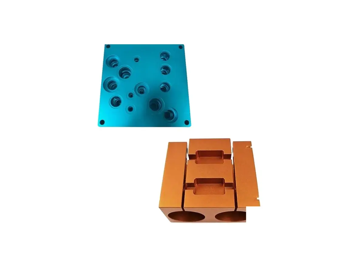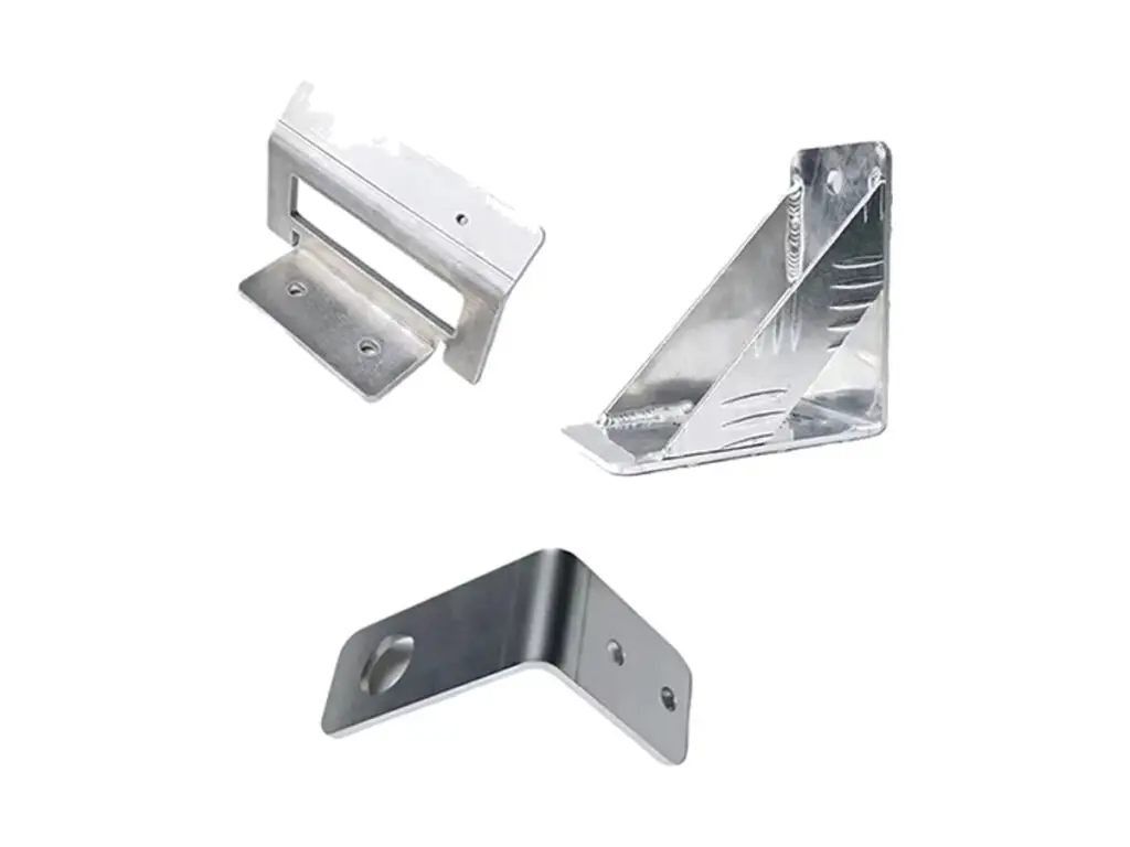


CNC Machined Aluminum Robot Mounting Brackets
CNC machined aluminium mounting brackets for robot bases, gantries and sensor frames, supplied as matched left and right pairs with an integral gusset. The right angle is held to 0.05 mm over the leg length, the hole pattern is transferred from the mating interface, and each pair is compared before packing.
- Matched Pairs
- Right Angle to 0.05 mm
- Gusseted for Stiffness
- Hole Pattern Transferred
*Tell us the bolt pattern on both the machine frame and the device. Drilling from the bracket outline instead of the interface is what leaves a slotted hole on assembly.
Robot Mounting Bracket Overview
A pair of brackets is only useful if the two halves agree. If they are machined separately, the left and right legs end up a few hundredths apart and the device sits twisted, which is normally corrected with shims that hide the real error.
Each pair is milled from a single plate, with the gusset cut integrally and the hole pattern transferred from the mating interface. The two halves are measured against each other before anodizing, and any pair outside 0.03 mm is re-machined rather than shipped.
6061-T6 Aluminium Plate
6061-T6 is the default for brackets because it holds a right angle through machining and anodizing, and it is light enough that a pair can be handled during installation. It takes a tapped thread well down to M4.
7075-T6 for Load-Bearing Pairs
7075-T6 is used when the brackets carry a heavy device or sit in a vibrating frame, since the gusset can be thinner for the same stiffness. It is harder to anodize to a matching colour across a pair.
For a pair that must match visually, 6061 is the safer alloy; for a pair that must not flex, 7075 with a deeper gusset is the better trade.
Robot Mounting Bracket Specifications
Milling data for bracket pairs, with the angle, hole position and pair-match values that decide whether the device sits square.
| Specification | Machining Data | Specification | Machining Data |
|---|---|---|---|
| Product | Robot / Automation Mounting Bracket (Pair) | Machining Process | CNC Milling, 4-Axis for Angled Faces |
| Material | 6061-T6 Aluminium Plate | Right Angle Tolerance | 0.05 mm Over the Leg Length |
| Leg Length | 40 – 250 mm | Hole Position | ±0.03 mm From Datum |
| Plate Thickness | 5 – 16 mm | Flatness per Leg | 0.05 mm |
| Gusset | Integral Rib 4 – 10 mm, or Pocketed Web | Pair Match | 0.03 mm Between Left and Right |
| Hole Work | Drilled, Reamed, Counterbored, Tapped M4 – M12 | Surface Finish | Ra 1.6 µm Faces, Ra 3.2 µm Edges |
| Edge Condition | 0.3 – 0.5 mm Break, Deburred by Hand | Anodizing | Type II 10 – 15 µm or As Machined |
| Customization | Leg Length, Gusset Shape, Slot Pattern, Marking | Lead Time | 5 – 8 Days (Pair), 10 – 14 Days (Batch) |
| Inspection | Angle Check, CMM Hole Pattern, Pair Comparison | Packing | Paired and Bagged Together, Carton |
Key Features of Our Bracket Pairs
Cut as a pair, measured as a pair, packed as a pair.
Integral Gusset, Not Welded
The rib is milled from the same plate as the legs, so the bracket has no weld seam to move during anodizing or to crack under vibration.
Right Angle Machined, Not Bent
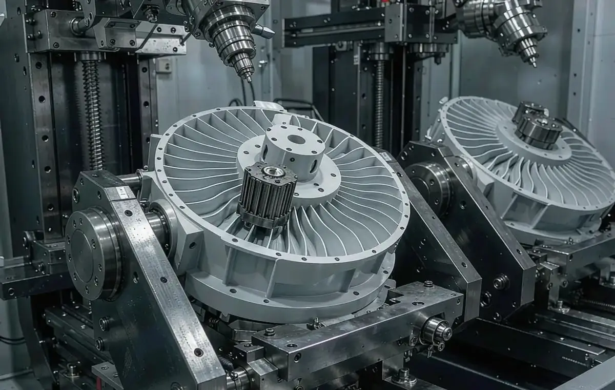
The 90° corner is cut in a 4-axis set-up rather than formed on a brake, which holds the angle to 0.05 mm and keeps the grain direction consistent.
Hole Pattern From the Interface
Holes are located from the mating drawing rather than the bracket outline, removing the tolerance stack that forces slots on assembly.
Left and Right Compared
Each pair is measured against its mirror before packing, and a pair outside 0.03 mm is re-machined instead of being sent with a shim note.
Need a bracket pair that bolts on square?
Surface Finishes for Mounting Brackets
When a pair is visible, the colour match matters as much as the coating thickness, so both halves are anodized in the same load.
| Finish | Main Purpose | Finish | Main Purpose |
|---|---|---|---|
| As Machined | Bare milled face for brackets hidden inside a frame | Type II Anodizing | Colour coding and corrosion protection |
| Bead Blasting | Matte uniform face that hides tool marks | Hard Anodizing | Wear resistance where the bracket is adjusted |
| Laser Marking | Left and right marking plus part number | Chromate Conversion | Conductive finish for earthed frames |
*Anodizing builds 5 to 7 µm per surface at Type II 10 to 15 µm, which tightens a tapped hole. Threads are cut to a pre-plate size or masked when the fit matters.
Put your CNC milling parts into production today
All information and uploads are secure and confidential.
Trusted for Precision CNC Machined Components
Supporting OEM projects with accurate machining, flexible production, and reliable component quality.
Trusted for Precision CNC Milling.
Milling Process for Bracket Pairs
Each pair is milled from one plate and compared against its mirror, so a left and right bracket bolt on without shimming.
01. Interface and Load Review
Check both bolt patterns, the device weight and the gusset height against the drawing, and confirm which leg carries the load before programming.
02. Plate Cutting and Facing
Cut both halves from one plate, face the datum faces and mark them, since the angle and the hole pattern are both cut from that surface.
03. Mill Legs, Gusset and Holes
Mill the profile, cut the integral gusset, then drill, ream and tap the hole pattern in the same set-up so the pattern stays on datum.
04. Deburr and Compare
Break all edges by 0.3 to 0.5 mm, then measure the pair against each other on the CMM and correct anything outside 0.03 mm.
05. Anodize and Pack as a Pair
Anodize both halves in the same load for colour match, then bag them together with the left and right marks visible on the label.
Send both bolt patterns and the device weight, and we will quote the pair with the gusset and hole pattern worked out.
Robot Mounting Bracket FAQs
Yes, but the pair is the usual order because the mirror is programmed from the same model at almost no extra setup. A single bracket is priced with the same programming cost.
Within 0.05 mm over the leg length, measured on a CMM rather than with a square. That is roughly a third of the error a folded bracket shows after anodizing.
Either. Tapped holes are cut to a pre-plate size when the bracket is anodized, and clear holes can be counterbored or slotted if the mating part needs adjustment.
Yes, when both halves are anodized in the same load, which is how they are processed. Colour is checked against a physical sample rather than a Pantone number.
12 to 16 mm with a gusset to about half the leg height. Thinner plate deflects at the free end under a cantilevered load, and the deflection shows as a misaligned sensor.
Five to eight days including programming, machining, anodizing and pair comparison. Batches of 50 pairs run ten to fourteen days depending on the number of colours.
Other CNC Machined Mechanical Components
Explore additional precision CNC machined components manufactured for OEM applications and customized production needs.
Custom CNC machined and anodized robot mounting brackets in 6061-T6 or 7075-T6.
Custom five-axis CNC milled aluminum impellers for centrifugal fans, blowers and vacuum pumps.
Custom CNC machined aluminium link brackets for automation linkages and robot assemblies.
Custom CNC machined aluminium manifold blocks for hydraulic and pneumatic circuits.
Custom Engine Mount CNC Milled parts manufactured through precision CNC machining.
Get high‑quality machined parts in as fast as 4 days with our expanded automated CNC milling!