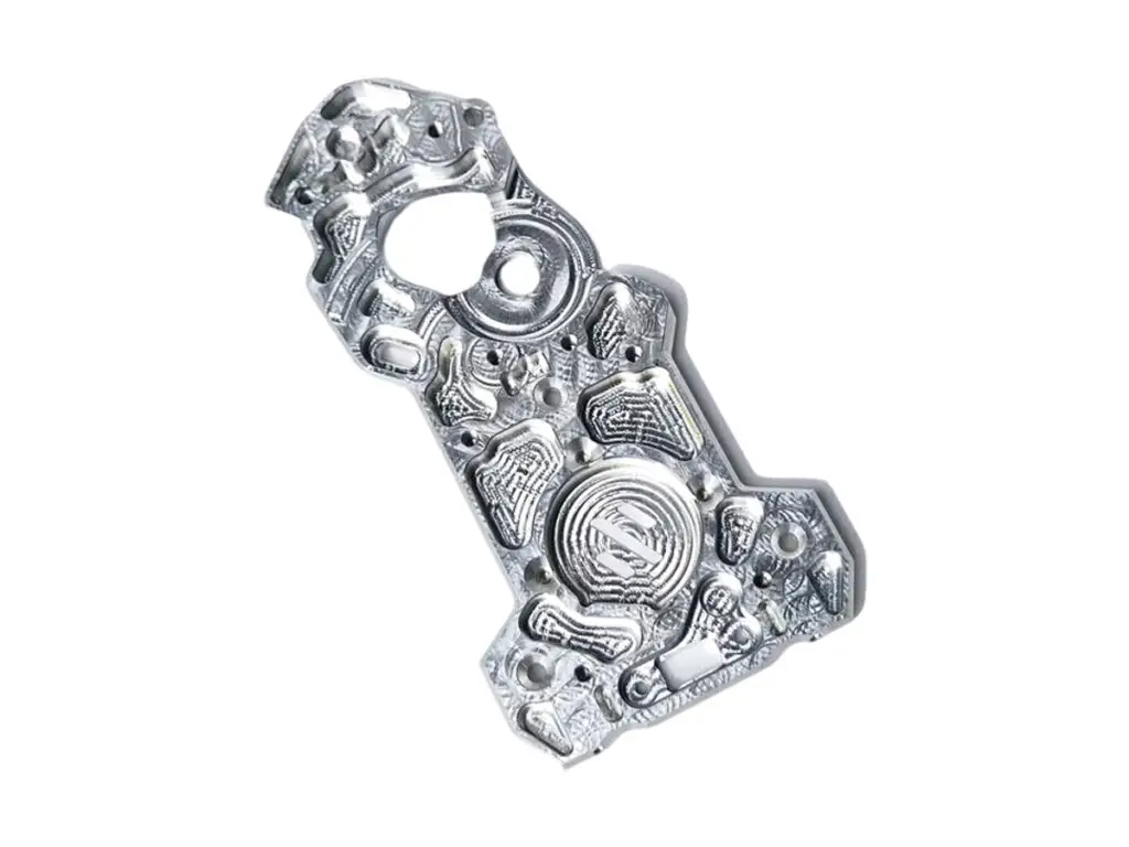


Five-Axis CNC Machined Aluminum Gearbox End Cap
Gearbox end caps five-axis machined from 6061-T6 billet, with a boss on a compound angle held to ±0.05°, a bearing seat bored to H7 and 0.012 mm roundness, a joint face flat to 0.03 mm and cooling fins cut to 3 mm without taper. The seat, the seal bore and the joint face are all machined from the same datum in one set-up.
- Boss on a Compound Angle
- Bearing Seat H7 in One Set-up
- Fins Cut Without Taper
- Joint Face Leak Tested
*Send the gearbox assembly model, not just the cap. The boss angle is set by the shaft it carries, and a cap machined to a cap drawing alone will point the shaft at the wrong place.
Gearbox End Cap Overview
An angled end cap carries a bearing or a seal on a face that is not square to the gearbox joint. That single fact makes it a five-axis part: the boss axis and the joint face have to be machined from one datum or the shaft misaligns.
The joint face is machined first, then the part is rotated on a trunnion to bring the boss axis upright for boring. Fins are cut after boring so the wall does not spring, and the seal bore is finished in the same set-up as the bearing seat.
6061-T6 Aluminium Billet
Billet is used because the boss has to be machined out of solid to keep the wall continuous around the bearing seat. 6061 machines fast and anodizes evenly across the fin edges, which are the first place a coating looks patchy.
7075-T6 or A356 Casting
7075-T6 is chosen when the cap also carries the reaction torque of the gearbox and the boss wall is thin. A356 casting is used above 500 units, where the fins and the boss can be cast and only the seat and joint face machined.
The fins decide the process: machined fins are stronger and thinner, cast fins are cheaper but need at least 4 mm of thickness to fill.
Gearbox End Cap Specifications
Five-axis data for angled end caps, with the boss, seat and joint values that keep the shaft aligned.
| Specification | Machining Data | Specification | Machining Data |
|---|---|---|---|
| Product | Gearbox End Cap / Angle Drive Cover | Machining Process | 5-Axis CNC Milling, Boring, Tapping |
| Material | 6061-T6 Aluminium Billet | Envelope | Up to 280 × 240 × 130 mm |
| Bearing Seat | Ø 25 – 90 mm, H7, Roundness 0.012 mm | Boss Angle | Any Compound Angle, ±0.05° |
| Joint Face | Flatness 0.03 mm, Ra 1.6 µm | Boss Position | ±0.05 mm on the Joint Face |
| Cooling Fins | Thickness 3 mm, Pitch 8 – 15 mm | Wall Thickness | 4 – 10 mm |
| Bolt Pattern | M6 – M12, Position ±0.05 mm | Oil Seal Bore | Ø 20 – 70 mm, H8 |
| Customization | Breather, Drain Plug, Sensor Boss, Logo Pocket | Lead Time | 7 – 9 Days Sample, 14 – 18 Days Batch |
| Inspection | CMM Boss Angle and Seat, Air Gauge Seat, Leak Test | Packing | Seat Plugged, Foam Cradle, Carton |
Key Features of Our End Caps
Boss and seat from one datum, fins after boring.
Boss Machined on a Trunnion
The compound angle is set by rotating the part, not by an angled fixture, so the boss axis is held to ±0.05° from the joint face.
Seat and Seal Bore in One Set-up
The bearing seat and the oil seal bore are bored without reclamping, so they are concentric and the seal does not run off-centre.
Fins Cut After Boring
Cooling fins are machined after the seat is finished, because removing 30 % of the wall before boring lets the seat spring oval.
Joint Face Leak Tested
The assembled cap is leak tested at working pressure, so a porous billet or a damaged joint face is caught before the gearbox is filled.
Cap with a boss on an angle?
Surface Finishes for End Caps
The joint face and the seat are fits; the fins are a heat path and a visible surface.
| Finish | Main Purpose | Finish | Main Purpose |
|---|---|---|---|
| Type II Anodizing | Corrosion protection on the outside | Hard Anodizing | Wear resistance in the seal bore |
| Masked Joint Face | Keeps the sealing face flat and bare | Bead Blasting | Even matte before dye on the fins |
| Laser Marking | Oil level and breather direction | Chromate Conversion | Conductive finish for an earth strap |
*Anodizing is an insulator and grows 5 to 10 µm. Joint faces and seats are masked, otherwise the cap loses both its seal and its bearing fit.
Put your CNC milling parts into production today
All information and uploads are secure and confidential.
Trusted for Precision CNC Machined Components
Supporting OEM projects with accurate machining, flexible production, and reliable component quality.
Trusted for Precision CNC Milling.
Five-Axis Machining Process
The angled boss and the bearing seat are machined without reclamping, so the shaft it carries lines up with the gear it drives.
01. Assembly Model Review
Check the cap against the gearbox assembly, confirm the boss angle, the bearing size and the seal bore before programming the trunnion set-up.
02. Machine the Joint Face
Face the joint side flat to 0.03 mm and establish it as datum A, then profile the outside so the part can be held for the angled operations.
03. Rotate and Bore the Boss
Rotate the part to bring the boss axis upright, face the boss, bore the bearing seat and the seal bore, and check the angle on the CMM.
04. Cut the Cooling Fins
Machine the fins with a small cutter at constant step-over so the 3 mm walls do not taper, then deburr the fin roots.
05. Drill, Test, Finish
Drill the bolt pattern and breather, leak test the joint, mask the seat and joint face, anodize and plug the bores for packing.
Send the assembly model and the bearing drawing, and we will quote a cap with the boss on its true angle and the seat bored in one set-up.
Gearbox End Cap FAQs
Because the boss that carries the bearing is usually not square to the joint face. On a three-axis machine that needs an angled fixture, and the angle error from the fixture lands directly in the shaft alignment.
±0.05° from the joint face, verified on the CMM by measuring the boss axis in two planes. Tighter is possible but needs the part to be machined in a temperature-controlled room.
Down to 2 mm with a light finishing pass, but the fin will ring during machining and may deflect in service. 3 mm is the practical minimum for a machined aluminium fin.
With an O-ring or a formed-in-place gasket on a face flat to 0.03 mm, and the assembled cap is leak tested before shipping. The face is masked during anodizing so it stays flat and bare.
No, it ships with the seat plugged and protected. Fitting the bearing is left to the gearbox builder so preload and end float stay under their control.
Yes, from the mating drawing or a measured sample, drilled to ±0.05 mm. The pattern is machined from the joint face datum, so it lines up with the housing dowels.
Other CNC Machined Mechanical Components
Explore additional precision CNC machined components manufactured for OEM applications and customized production needs.
Custom CNC machined aluminum double tube clamps for motorcycle frames, bicycle builds and hydraulic lines.
Custom CNC machined hardened steel sleeves for robotic joints and motion assemblies.
Custom CNC machined aluminium fuel pump blocks for automotive and motorsport fuel systems.
Explore CNC milled UAV frames in 6061 or 7075 aluminum, built for lightweight structures, accurate assembly, component.
CNC machined 4140 alloy steel spur gears with hobbed teeth to DIN 6, bore and face square to 0.02 mm, induction hardened to 50.
Get high‑quality machined parts in as fast as 4 days with our expanded automated CNC milling!