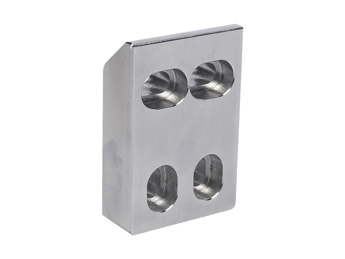
Home / CNC-Machining / CNC-Turning / CNC Turned Steel Threaded Flange Base
Steel threaded flange base turned with an internal thread, a spigot and a machined flange face

CNC Turned Steel Threaded Flange Base

CNC turned steel threaded flange bases that mount a threaded component onto a flat face, with the internal thread concentric to the spigot within 0.02 mm and the flange face square to the thread axis within 0.02 mm. Machined in 1045 or 4140 and finished black oxide, zinc or bare for welding.

*Tell us which feature is the datum: the thread, the spigot or the bolt circle. Mounting hubs are often checked against the OD, which is the one feature that does not control the fit.

Steel Threaded Flange Base Overview

A threaded flange base joins a threaded component to a flat mounting face, so it has to control two things at once: the thread axis and the face the mating part sits on. If the face is not square to the thread, the component leans and the load goes to one side of the thread.

The part is turned from bar or a cut blank, the thread is cut first, and the flange face and spigot are machined in a second operation held on the thread, so the face is square to the thread rather than to the bar end. The bolt circle is drilled from the same centre.

Assembly and inspection of a rod end clevis, a slotted drive hub and a split clamp ring
304L stainless steel round bar stock for CNC machining

1045 Carbon Steel

1045 is used for flange bases that carry moderate load and are plated, because it machines to a clean thread and takes a uniform zinc or black oxide finish. It is the lower-cost option for general mounting work.

304L stainless steel plate and block stock for CNC machining

4140 for Higher Strength

4140 is chosen when the flange carries a bending moment or the thread has to hold preload without yielding. It can be supplied through-hardened to 28 to 32 HRC for wear on the thread flanks.

For a static mount, 1045 with zinc is enough. For a hub that sees vibration or repeated assembly, 4140 with phosphating resists galling and fatigue better.

Threaded Flange Base Specifications

Turning and threading data for flange bases, with the thread, spigot and squareness values that decide whether the mounted part runs true.

SpecificationMachining DataSpecificationMachining Data
ProductThreaded Flange Base / Mounting HubMachining ProcessCNC Turning, Threading, Face and Spigot Turning
Material1045 or 4140 Alloy SteelThread Tolerance6H Internal, Gauged
Flange Diameter30 – 200 mmThread to Spigot Concentricity0.02 mm
Thread RangeM10 × 1 to M48 × 2, or BSP / NPTFlange Face Squareness0.02 mm to Thread Axis
Spigot Diameter15 – 120 mm, h7Spigot to Thread Coaxiality0.02 mm
Overall Height20 – 120 mmSurface FinishRa 1.6 µm Spigot, Ra 3.2 µm Flange Face
Mounting Holes3 to 8 Holes on a Bolt Circle, M6 to M16Hardness (Optional)28 – 32 HRC Through Hardened
CustomizationThread Size, Spigot, Bolt Circle, Keyway, MarkingLead Time7 – 10 Days (Sample), 13 – 17 Days (Batch)
InspectionThread Gauge, Spigot Micrometer, CMM Squareness, Bolt CirclePackingThread Cap, Oil-Filmed, Bagged, Carton

Key Features of Our Threaded Flange Bases

Threaded first, faced against the thread, drilled from the same centre.

Flange Face Finished Against the Thread

The face is machined in a second operation held on the thread, so it is square to the thread axis within 0.02 mm rather than to the sawn end of the bar.

Spigot Coaxial to the Thread

The spigot is turned on the same axis as the thread, keeping the locating diameter and the thread within 0.02 mm so a mounted part cannot lean.

Threads Gauged Both Ways

Internal threads are checked with go/no-go plug gauges, and any thread that fails is re-cut or scrapped rather than sent with a sealant note.

Bolt Circle From the Thread Centre

Mounting holes are drilled from the thread axis, so the bolt pattern stays concentric even when the flange OD is machined to a loose tolerance.

Need a hub that mounts square to a thread?

Surface Finishes for Threaded Flange Bases

Plating builds on the thread flanks, so any coated hub is threaded to a pre-plate size and gauged afterwards.

FinishMain PurposeFinishMain Purpose
Black OxideCorrosion protection with no dimensional change on threadsZinc PlatingSacrificial protection for outdoor mounting
PhosphatingOil-retaining surface that resists galling on threadsElectroless NickelUniform coating on threads and spigot for cleanroom use
Rust-Preventive OilStorage protection before assemblyNone (Bare)Where the flange is welded or painted after assembly

*Zinc plating adds 8 to 12 µm and tightens an internal thread. Coated hubs are tapped 0.02 mm oversize and the thread is gauged after plating.

logo

Put your CNC milling parts into production today

All information and uploads are secure and confidential.

Trusted for Precision CNC Machined Components

Supporting OEM projects with accurate machining, flexible production, and reliable component quality.

Mechanical Equipment Customer
Internal thread starts clean, so the column screws in by hand all the way to the shoulder.

Industrial Components Buyer
Flange face is square to the thread, so the base sits flat without rocking.

Equipment Manufacturer
Spigot diameter matched, so the base centres in the frame without a jig.

OEM Customer
OEM Customer
They cut the thread to a pre-plate size, so it still fits after the coating.

Automation Industry Customer
The customized machining solution provided the dimensional accuracy required for our rotating equipment components.

Trusted for Precision CNC Milling.

Turning Process for Threaded Flange Bases

The thread, the spigot and the flange face are cut on one axis, so the mounted part runs true to the thread rather than to the outside diameter.

01. Interface Review

Check the mating thread, the face it seats on and the bolt circle, then confirm which feature is the datum before the blank is cut.

02. Blank and Thread

Cut the blank, face it, turn the OD and cut the internal thread, holding the thread to 6H and gauging it before the second operation.

03. Second Op Face and Spigot

Hold the part on the thread, face the flange, turn the spigot to h7 and cut the relief so the face and spigot share the thread axis.

04. Bolt Circle and Deburr

Drill the bolt circle from the thread centre, deburr the holes and break the flange edge by 0.5 mm so the plated edge does not flake.

05. Finish, Gauge and Pack

Apply black oxide, zinc or bare finish, gauge the thread after coating, check squareness on a CMM, then cap the thread and oil-film the part.

Send the mating thread, the mounting face and the bolt circle, and we will quote the hub with the datum and finish fixed.

Threaded Flange Base FAQs

Usually the thread, because it is what the mounted component engages. The flange face and spigot are then machined against it, so the component sits square instead of leaning on the OD.

It can, but welding distorts the face and the thread. Weld preparation is machined and the thread is cut after welding, or the part is supplied bare and finished after the weld.

0.02 mm to the thread axis, measured on a CMM with the part held on a threaded mandrel. That is tight enough to keep a mounted motor or sensor from leaning under load.

Yes, BSPP, BSPT and NPT are cut and gauged with the matching plug gauge. Taper threads are checked for engagement depth as well as size.

Yes, by 8 to 12 µm on zinc. Coated parts are tapped oversize and gauged after plating, so the mating component still threads in by hand.

Seven to ten days for a sample including turning, threading, finishing and CMM. Batches of 50 to 300 pieces run thirteen to seventeen days depending on the finish.

Other CNC Machined Mechanical Components

Explore additional precision CNC machined components manufactured for OEM applications and customized production needs.

Precision CNC machined aluminum connecting plates for robot modules and automation equipment.

Custom CNC machined aluminium drone components, including arm mounts, motor mounts and frame fittings.

Custom CNC machined aluminium filament stand brackets for 3D printer spool holders.

Custom CNC machining milling aluminum robot base frames for industrial robots and automation equipment.

316L stainless fluid manifold blocks machined from solid with flat port faces to 0.02 mm, drilled galleries cleared by borescope.

Get high‑quality machined parts in as fast as 4 days with our expanded automated CNC milling!

Scroll to Top