

Home / CNC-Machining / CNC-Turning / CNC Turned Aluminum V-Belt Pulley
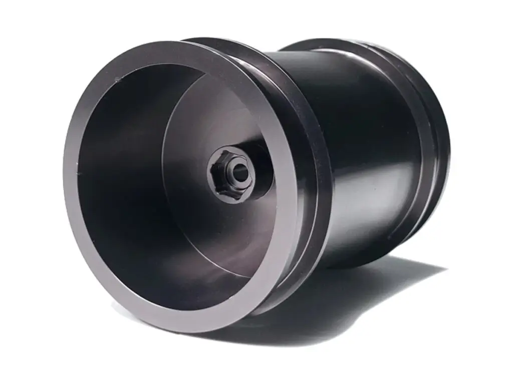
CNC turned aluminum V belt pulley with a machined groove profile

CNC Turned Aluminum V-Belt Pulley

V-belt pulleys turned from 6061-T6 bar, with a groove profile held to ±0.05 mm on angle and depth, groove pitch to ±0.03 mm, bore ground to H7, radial runout of 0.03 mm on the flanks and residual unbalance to G6.3 at 3,000 rpm. Keyways are cut after boring and the rim is balanced before anodizing.

*Send the belt section and the shaft diameter. The groove angle changes with the belt section, and a pulley cut for an A section will not hold a B belt at the right depth.

V-Belt Pulley Overview

A V-belt pulley transmits torque through friction on two flanks, so the groove angle, the groove depth and the pitch diameter all have to be right. A groove that is too deep lets the belt bottom out and slip; too shallow and the belt rides high and wears.

The pulley is turned from bar or plate, the groove is cut with a form tool and checked with a profile gauge, then the bore is bored and ground. Keyways are cut after boring so the broach does not distort the bore, and the part is balanced before coating.

CNC turning of a brass threaded flange bushing, an aluminum bearing sleeve and a retaining cover disc
6061-T6 aluminium round bar stock for CNC turning

6061-T6 Aluminium Bar

6061-T6 is the usual choice for light-duty pulleys because it is strong enough for the rim speed, machines to a clean groove and anodizes hard enough to resist belt wear. It also keeps the inertia low on start-stop drives.

7075-T6 aluminium round disc blank for CNC machining

7075-T6 or Cast Iron

7075-T6 is used on high-speed or high-torque drives where the rim must not grow. Cast iron is specified where the pulley is a wear part and the belt runs continuously, because it holds the groove profile far longer.

Aluminium suits drives under about 15 kW and intermittent duty; above that, cast iron or steel is cheaper over the life of the groove.

V-Belt Pulley Specifications

Turning data for V-groove pulleys, with the groove, bore and balance values that decide whether the belt runs true.

SpecificationMachining DataSpecificationMachining Data
ProductV-Belt Pulley / Single and Multi-GrooveMachining ProcessCNC Turning, Grooving, Boring, Balancing
Material6061-T6 Aluminium BarDiameter RangeØ 60 – 400 mm
BoreØ 10 – 80 mm, H7, GroundGroove Profile±0.05 mm on Angle and Depth
Groove Pitch±0.03 mm Between GroovesRadial Runout0.03 mm on the Groove Flanks
Axial Runout0.02 mm on the Rim FaceBalanceG6.3 at 3,000 rpm
KeywayWidth ±0.02 mm, Depth ±0.05 mmWall Thickness6 – 20 mm at the Hub
CustomizationTaper Lock Bush, Split Hub, Lightening HolesLead Time5 – 7 Days Sample, 12 – 16 Days Batch
InspectionGroove Profile Gauge, Bore Air Gauge, Runout Between Centres, Balance ReportPackingFoam Ring, Individually Boxed, Crate

Key Features of Our V-Belt Pulleys

Groove gauged, bore ground, rim balanced.

Groove Checked With a Profile Gauge

Every groove is checked against the belt section gauge, so the belt sits at the correct depth and does not bottom out under load.

Bore Ground to H7

The bore is ground rather than reamed, which holds the fit and the concentricity that keeps the pulley from running out at speed.

Keyway Cut After Boring

Broaching a keyway distorts the bore, so the keyway is cut last and the bore is checked again before the pulley is balanced.

Balanced Before Coating

The rim is balanced by removing material from the inside face, not the groove, and the balance mark is transferred to the finished part.

Pulley that has to run without vibration?

Surface Finishes for V-Belt Pulleys

The groove flanks are the working surface; the bore and keyway are fits; the rest is cosmetic.

FinishMain PurposeFinishMain Purpose
Type II AnodizingCorrosion protection and colour codingHard AnodizingWear resistance in the V-groove
Masked Bore and KeywayKeeps the shaft fit at H7Bead BlastingEven matte before dye
Laser MarkingPulley size and balance markBare Groove FlanksUses the aluminium surface as the belt running face

*Hard anodizing in the groove raises the surface by 25 to 50 µm and changes the effective pitch diameter. Grooves can be masked, or machined undersize and finished after coating.

logo

Put your CNC milling parts into production today

All information and uploads are secure and confidential.

Trusted for Precision CNC Machined Components

Supporting OEM projects with accurate machining, flexible production, and reliable component quality.

Mechanical Equipment Customer
The belt sits at the right depth in the groove and does not bottom out under load.

Industrial Components Buyer
No vibration at running speed, and the bearing temperature dropped after the swap.

Equipment Manufacturer
The bore was a proper H7 fit, so the pulley went on without a press.

OEM Customer
OEM Customer
Groove pitch matched the old pulley, and the belt runs on the same line.

Automation Industry Customer
The customized machining solution provided the dimensional accuracy required for our rotating equipment components.
Trusted for Precision CNC Milling.

Turning Process for V-Belt Pulleys

The V-groove is turned and checked with a profile gauge before the bore is finished, so the belt sits at the right depth instead of bottoming out.

01. Belt and Shaft Review

Confirm the belt section, the number of grooves and the shaft fit, then choose the groove tool and the bore allowance.

02. Turn the Blank

Face, centre and turn the outside diameter and both faces, leaving 0.3 mm on the groove flanks and 0.2 mm in the bore.

03. Cut the Grooves

Cut each groove with a form tool at constant feed, check the profile with a gauge and measure the pitch between grooves before parting off.

04. Bore, Keyway and Balance

Bore and grind the bore to H7, cut the keyway, then balance the pulley and mark the correction position on the rim.

05. Anodize and Inspect

Mask the bore and keyway, anodize, then check runout between centres and record the balance before packing each pulley in foam.

Send the belt section and the shaft diameter, and we will quote a pulley with the groove gauged and the bore ground to H7.

V-Belt Pulley FAQs

Yes, any angle from 34° to 40° held to ±0.05°, machined with a form tool ground to the angle. The gauge is made to the same angle so the check is meaningful.

Because at 3,000 rpm a 300 mm pulley with 20 g of unbalance produces enough force to wear the bearing. Balancing removes material from the inside face, away from the groove.

Yes, by 5 to 10 µm per surface in Type II and 25 to 50 µm in hard anodizing. Grooves that must stay on size are masked, or the pulley is machined undersize and finished after coating.

Yes, the hub is bored and machined to the bush drawing, with the split and the screw holes positioned so the bush pulls the pulley onto the shaft squarely.

The bore is machined in the same set-up as the groove, or ground between centres afterwards, holding concentricity to 0.02 mm so the belt does not run out of line.

400 mm diameter. Above that the pulley is machined as a rim and a hub, then bolted and dowelled, which keeps the groove accurate but adds a joint.

Other CNC Machined Mechanical Components

Explore additional precision CNC machined components manufactured for OEM applications and customized production needs.

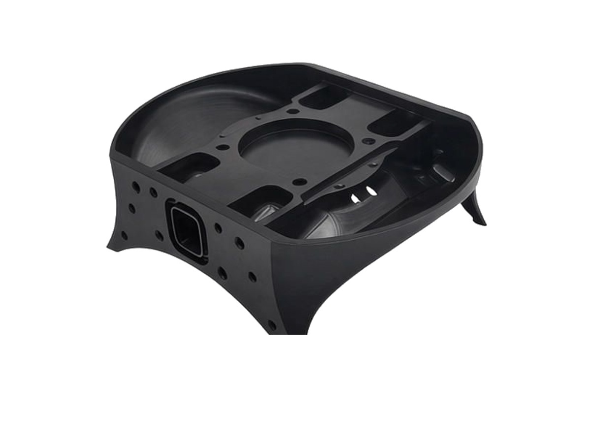
Custom CNC machined aluminium cavity bases for automation and electronic equipment.

Explore CNC milled clutch levers in 6061 or 7075 aluminum, built for smooth pivot movement, accurate fit, comfortable control,.

Custom CNC machining milling aluminum engine brackets with 6061/7075 aluminum, complex milling, multiple finishes and precision.

CNC milled aluminium servo motor mounting bases with a bored pilot register, face flat to 0.02 mm and shaft centre height held to.

Custom CNC machined steel hydraulic manifold blocks with cross-drilled galleries and gauged ports.

Get high‑quality machined parts in as fast as 4 days with our expanded automated CNC milling!

Scroll to Top