

CNC Milled Aluminum Servo Motor Mounting Base
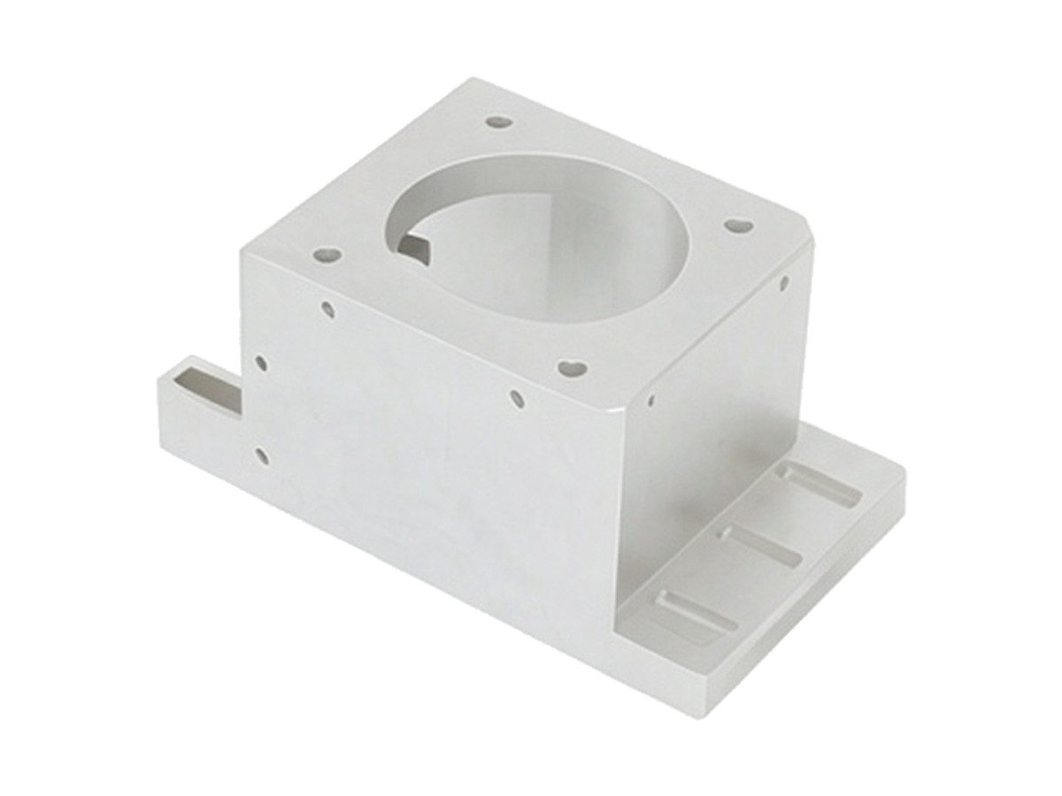
CNC milled aluminium servo motor mounting bases for belt, coupling and rack drives, with a bored pilot register held to H7, shaft centre height to ±0.02 mm and a mounting face flat to 0.02 mm. Belt windows and slotted holes are cut in the same set-up as the bore, so tensioning does not move the motor off axis.
- Pilot Register Bored to H7
- Centre Height ±0.02 mm
- Face Flat to 0.02 mm
- Red or Black Anodizing
*Give us the motor drawing, not just the frame size. Pilot diameter, bolt circle and shaft length vary between manufacturers, and the centre height depends on all three.
Servo Motor Mounting Base Overview
A motor base is a height reference as much as a bracket. The shaft has to sit at a fixed centre height so the belt runs true, and the pilot register has to be concentric with the bolt circle so the motor does not sit cocked on its flange.
The base is milled from plate, the mounting face is faced flat, and the pilot bore is bored rather than interpolated so it stays round. Centre height is measured from the base to the bore axis, and both are cut from the same datum so the number holds after anodizing.
6061-T6 Aluminium Plate
6061-T6 is used for motor bases because it is stiff enough to hold centre height under belt tension and light enough not to add inertia to a moving gantry. It anodizes evenly on a visible machine frame.
7075-T6 for Heavy Drives
7075-T6 is chosen when the base carries a large servo through a belt reduction, where the overturning moment at the flange is high. It holds the pilot bore round at higher bolt torque.
The base thickness is set by the belt pull and the overhang, not by the motor size. A thin base under a small motor will still flex if the pulley is far from the mounting face.
Servo Motor Mounting Base Specifications
Milling and boring data for motor bases, with the pilot, centre height and flatness values that decide belt alignment.
| Specification | Machining Data | Specification | Machining Data |
|---|---|---|---|
| Product | Servo Motor Mounting Base / Frame | Machining Process | CNC Milling, Boring, Face Milling |
| Material | 6061-T6 Aluminium Plate | Pilot Register | H7 Bore, 0.02 mm Concentric to Bolt Circle |
| Motor Frame | NEMA 17 / 23 / 34, 60 – 130 mm Flange | Shaft Centre Height | ±0.02 mm From Base |
| Envelope | 80 × 80 × 40 mm to 250 × 200 × 120 mm | Mounting Face Flatness | 0.02 mm |
| Wall Thickness | 6 – 15 mm | Face Squareness to Base | 0.03 mm |
| Bolt Pattern | 4 Holes, M4 to M10, Slotted for Belt Tension | Bore Surface Finish | Ra 1.6 µm |
| Belt Access | Open Window or Slot for Belt and Pulley | Anodizing | Type II 15 – 20 µm, Red or Black |
| Customization | Centre Height, Window Shape, Slot Length, Marking | Lead Time | 6 – 8 Days (Sample), 12 – 16 Days (Batch) |
| Inspection | CMM Centre Height, Bore Gauge, Flatness, Bolt Circle | Packing | Foam Interleaved, Bagged, Carton |
Key Features of Our Motor Mounting Bases
Bored for concentricity, faced for height, slotted for tension without losing alignment.
Pilot Bore Bored, Not Interpolated
The register is bored with a single-point tool, so it stays round within 0.01 mm and the motor flange seats without rocking on a high spot.
Centre Height From the Base Datum
Centre height is measured from the mounting face to the bore axis in one set-up, which keeps the belt plane parallel to the driven pulley.
Tension Slots Keep the Axis
Slots are milled parallel to the belt direction so the motor can be tensioned without moving sideways, which is what usually throws a belt off a pulley.
Belt Window Cut Through
The belt window is cut through the base with a radiused corner, so the belt runs clear and the base keeps its stiffness around the bolt pattern.
Need a motor base at an exact centre height?
Surface Finishes for Servo Motor Bases
The pilot bore is a fit surface, so the coating is either kept out of it or the bore is sized after anodizing.
| Finish | Main Purpose | Finish | Main Purpose |
|---|---|---|---|
| Type II Anodizing | Colour coding and corrosion protection on the base | Hard Anodizing | Wear face where a belt or pulley rubs |
| Bead Blasting | Matte finish before dyeing so the colour is uniform | Masked Anodizing | Bare pilot bore where the motor register is a press fit |
| Laser Marking | Motor frame size and centre height on the base | Chromate Conversion | Conductive finish where the motor is earthed through the base |
*Anodizing adds 7 to 10 µm to the pilot bore. When the motor register is a close fit, the bore is masked, or bored 0.02 mm oversize and finished after dye.
Put your CNC milling parts into production today
All information and uploads are secure and confidential.
Trusted for Precision CNC Machined Components
Supporting OEM projects with accurate machining, flexible production, and reliable component quality.
Trusted for Precision CNC Milling.
Milling Process for Servo Motor Mounting Bases
The pilot bore is bored in the same set-up as the base face, so the motor shaft sits at the centre height the belt was designed around.
01. Motor and Drive Review
Check the pilot diameter, bolt circle, shaft length and belt pull against the drawing, and confirm the centre height the drive was designed around.
02. Plate Prep and Facing
Square the plate, face the base and the mounting face, then mark the datum so the bore, slots and window are all programmed from the same surface.
03. Bore and Bolt Pattern
Bore the pilot register to H7, drill and tap the motor bolts, and cut the tension slots parallel to the belt direction in the same set-up.
04. Window and Deburr
Mill the belt window through the base, break all edges by 0.3 mm and blend the window corners so the belt cannot chafe on a sharp edge.
05. Anodize, CMM and Pack
Mask the pilot bore if required, anodize to colour, measure centre height and flatness on a CMM, then pack with foam between bases.
Send the motor datasheet, the belt layout and the centre height, and we will quote the base with the bore and slots defined.
Servo Motor Mounting Base FAQs
Yes, measured from the base face to the bore axis on a CMM after anodizing. The face and the bore are cut in the same set-up, so the number does not depend on a second fixture.
Send the motor drawing with the pilot diameter and its tolerance. A clearance register is bored 0.02 to 0.05 mm over nominal; a location register is bored to the motor pilot with a light press fit.
Slots let the belt be tensioned without shimming the motor, and because they run parallel to the belt direction the motor stays on axis while it moves. Fixed holes require a separate tensioner.
Not if the wall between the bore and the base is at least 8 mm on a 100 mm frame. Thinner walls are reviewed against the belt pull before machining, and thickened if the overhang is long.
Yes. The same process is used for a gearbox flange, with the register bored to the gearbox spigot and the bolt circle matched to its output flange.
Six to eight days for a sample pair including programming, milling, boring and anodizing. Batches of 20 to 200 pieces run twelve to sixteen days depending on the number of colours.
Other CNC Machined Mechanical Components
Explore additional precision CNC machined components manufactured for OEM applications and customized production needs.
Custom CNC machined aluminum motor bases and mounting pedestals for servo and spindle motors.
Custom CNC machined and anodized robot mounting brackets in 6061-T6 or 7075-T6.
Custom five-axis CNC milled aluminum impellers for centrifugal fans, blowers and vacuum pumps.
Custom CNC machined aluminium link brackets for automation linkages and robot assemblies.
Custom CNC machined aluminium manifold blocks for hydraulic and pneumatic circuits.
Get high‑quality machined parts in as fast as 4 days with our expanded automated CNC milling!