
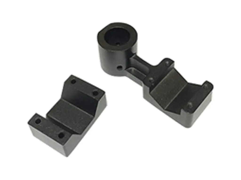


CNC Machined Anodized Clamp Jaw Block
Clamp jaw blocks cut from 6061-T6 and finished in black anodizing: a Ø22 H7 gripper bore round within 0.010 mm, jaw faces parallel to 0.02 mm, a 12 mm slot at ±0.05 mm and an 8 mm arm bore positioned to ±0.03 mm. Each pair is machined from the same billet, matched left and right, and numbered before coating.
- Ø22 H7 Gripper Bore
- Jaw Faces Parallel 0.02
- Square Within 0.03
- Black Anodized 20 µm
*Tell us the gripper model and the closing force. Above 400 N the jaw face needs a hardened insert, and a 0.02 mm taper across the face will make the part climb as it closes.
Anodized Clamp Jaw Overview
A gripper jaw looks simple until it has to repeat. The two faces must stay parallel through the closing stroke, the pivot bore must stay concentric with the gripper finger, and the body must be light enough that the robot does not lose acceleration. All three come from machining the pair together.
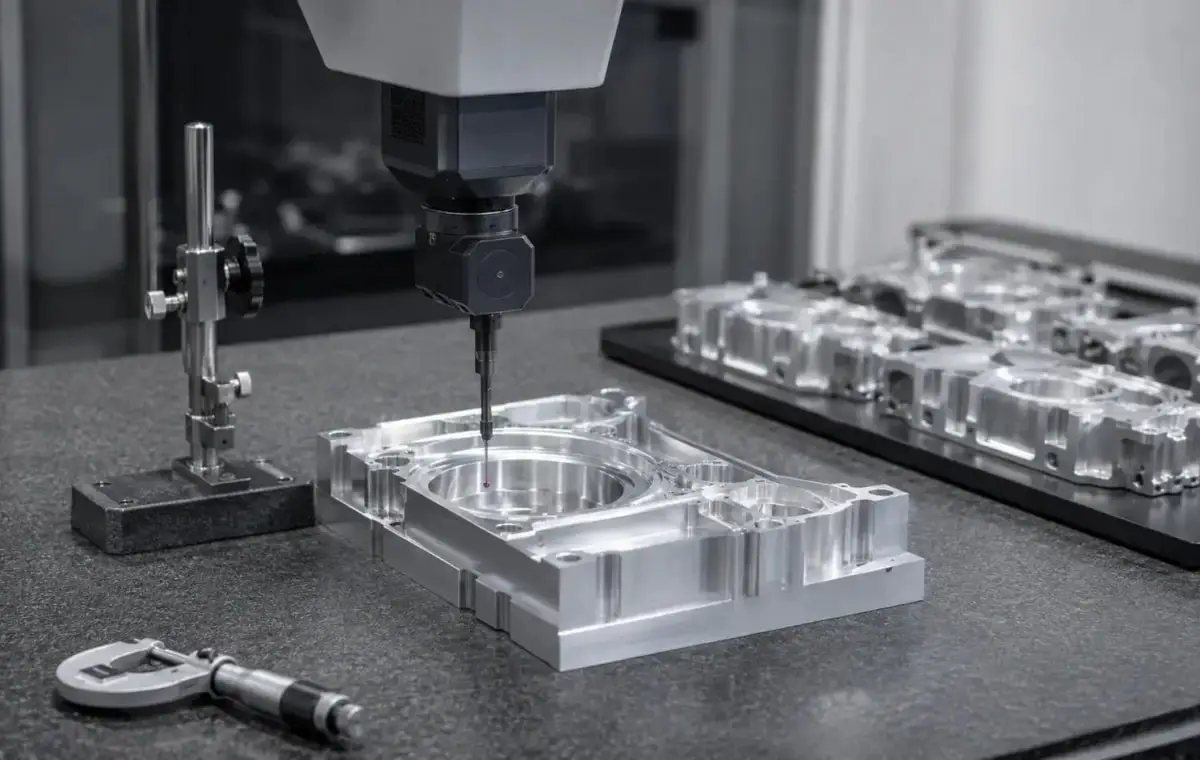
The pair is cut from one billet, the bore is bored in a single clamping and the jaw faces are fly-cut after the profile so they stay parallel to the pivot axis. The pair is numbered, anodized together and checked on the CMM as a set, not as two separate parts.
6061-T6 Aluminium
6061-T6 keeps the jaw at 95 g, anodizes to a hard 20 µm skin that resists scuffing and holds the pivot bore without galling against a steel pin.
7075-T6 or 6082-T6
7075-T6 is chosen when the jaw is thin and the closing force is high, and 6082-T6 is used for jaws that are welded to a custom finger.
A jaw under 8 mm at the pivot will flex under closing force and lose parallelism; the section is kept at 12 mm around the bore.
Clamp Jaw Block Specifications
Bore, face and pair data for gripper jaws, measured as a matched set.
| Specification | Machining Data | Specification | Machining Data |
|---|---|---|---|
| Product | Clamp Jaw Block and Arm | Process | CNC Milling, Boring, Profiling |
| Material | 6061-T6 Aluminium | Envelope | 95 × 45 × 38 mm per Jaw |
| Gripper Bore | Ø22 H7, Roundness 0.010 mm | Jaw Face | Parallelism 0.02 mm |
| Arm Bore | Ø8 H7, Position ±0.03 mm | Slot | 12 mm Wide, ±0.05 mm |
| Squareness | 0.03 mm Over 90 mm | Threads | 2 × M5 × 0.8, 10 mm Deep |
| Anodizing | Black, 18 to 22 µm | Weight | Approx. 95 g per Pair |
| Edge Break | 0.4 mm on All Handling Edges | Pair Matching | Serial Matched Left and Right |
| Inspection | CMM, Bore Gauge, Parallel Check | Batch Size | 20 to 1,000 Pairs |
| Finish | Black or Clear Anodizing | Drawing Format | STEP, DXF, PDF |
Pairs, Not Parts
One billet, one bore pass, one number on both jaws.
Matched Pair From One Billet
Both jaws are cut from the same billet so the grain, the heat treatment and the machining stress are identical, and the pair closes without one side springing more than the other.
Jaw Faces Fly-Cut Last
The gripping faces are fly-cut after the profile is finished, which removes the 0.03 mm bow left by the slot and brings the two faces parallel within 0.02 mm across the full 45 mm.
Bore and Pivot on One Axis
The Ø22 gripper bore and the Ø8 arm bore are cut in the same clamping, so the jaw rotates around the finger pin without binding at the end of the stroke.
Numbered Before Coating
Each pair is stamped with a serial before anodizing, so a replacement jaw can be matched to the original pair rather than replacing both.
Gripper jaw that has to repeat?
Surface Finishes for Clamp Jaws
The grip face is functional, the body is cosmetic, and the bore stays bare.
| Finish | Main Purpose | Finish | Main Purpose |
|---|---|---|---|
| Black Anodizing | Low-reflection gripper body | Clear Anodizing | General protection, visible wear |
| Hard Anodizing | Wear face on a sliding jaw | Bead Blasting | Matte before coating |
| Masked Bore | Bare bore for a press-fit pin | Laser Marking | Pair number and jaw side |
| Chromate Conversion | Conductive body for sensing | Teflon Insert | Low-friction jaw pad |
| Serrated Insert | Hardened steel jaw teeth | Deburr Only | Internal fixtures |
| Pair Numbering | Keeps a replacement jaw matched | Shim Check | Face parallelism verified after coating |
*Anodizing builds 20 µm on the jaw face and closes the bore; the bore is masked and the face is checked with a shim after coating.
Put your CNC milling parts into production today
All information and uploads are secure and confidential.
Trusted for Precision CNC Machined Components
Supporting OEM projects with accurate machining, flexible production, and reliable component quality.
Trusted for Precision CNC Milling.
How We Machine a Clamp Jaw Pair
The two jaws are machined as a matched pair, bored in the same set-up and numbered, so the gripper closes parallel instead of cocking on one side.
01. Gripper and Load Review
Check the gripper model, the closing force and the part being gripped, then decide whether the jaw face needs a hardened insert or a plain anodized face.
02. Cut the Pair From One Billet
Saw the billet into a matched pair, face both halves and mark the pair number on the top face before any profiling.
03. Profile and Slot
Rough the profile with a 10 mm end mill, cut the 12 mm slot with a 6 mm cutter at 0.3 mm step-down, then finish the outer profile.
04. Bore and Fly-Cut the Faces
Bore the Ø22 H7 and Ø8 H7 bores in one clamping, then fly-cut both jaw faces so they are parallel to the pivot axis within 0.02 mm.
05. Number, Anodize, Check as a Pair
Stamp the pair number, mask the bores, black anodize, then measure the pair on the CMM with the jaws closed.
Send the gripper model and the jaw drawing, and we will quote a matched pair with the faces parallel and the bore sized to your finger pin.
Clamp Jaw Block FAQs
Yes, from the gripper drawing or a sample jaw. The pivot bore and the face offset are the two dimensions we copy, and the mounting pattern follows the finger.
They should be. A single replacement jaw will not close parallel to a worn partner, so we machine and number in pairs and supply them as a set.
Black anodizing gives about 300 to 400 HV at 20 µm. For abrasive parts we fit a hardened steel insert at 58 HRC instead of relying on the coating.
Yes, with a 0.5 or 1 mm pitch serration milled before anodizing. Serrations are cut at 90 degrees to the closing direction so the part cannot slide out.
First articles in seven working days from an approved STEP file, with the pair photographed and measured before the batch runs.
The bore is masked, so the H7 fit is unchanged. If the bore is coated, it is reamed back to H7 after anodizing and checked with a plug gauge.
Other CNC Machined Mechanical Components
Explore additional precision CNC machined components manufactured for OEM applications and customized production needs.
CNC machined 7075-T6 aluminium gripper jaws cut as a matched pair, with the grip profile machined to your part, dowel holes to H7.
CNC turned brass slotted bushings with a honed bore, milled lubrication slots and a chamfered lead-in, held to 0.01 mm and.
Five-axis CNC machined aluminium gearbox end caps with a compound-angle boss, a bored bearing seat and cooling fins, machined in.
CNC machined aluminium perforated mounting plates with a lightening hole pattern, edge datum faces and counterbored fixings, flat.
CNC machined 6061-T6 aluminium mounting brackets with a machined mounting face, slotted holes and an even anodized finish, held.
Get high‑quality machined parts in as fast as 4 days with our expanded automated CNC milling!



