

CNC Machined Aluminum Twin-Bore Clevis Block
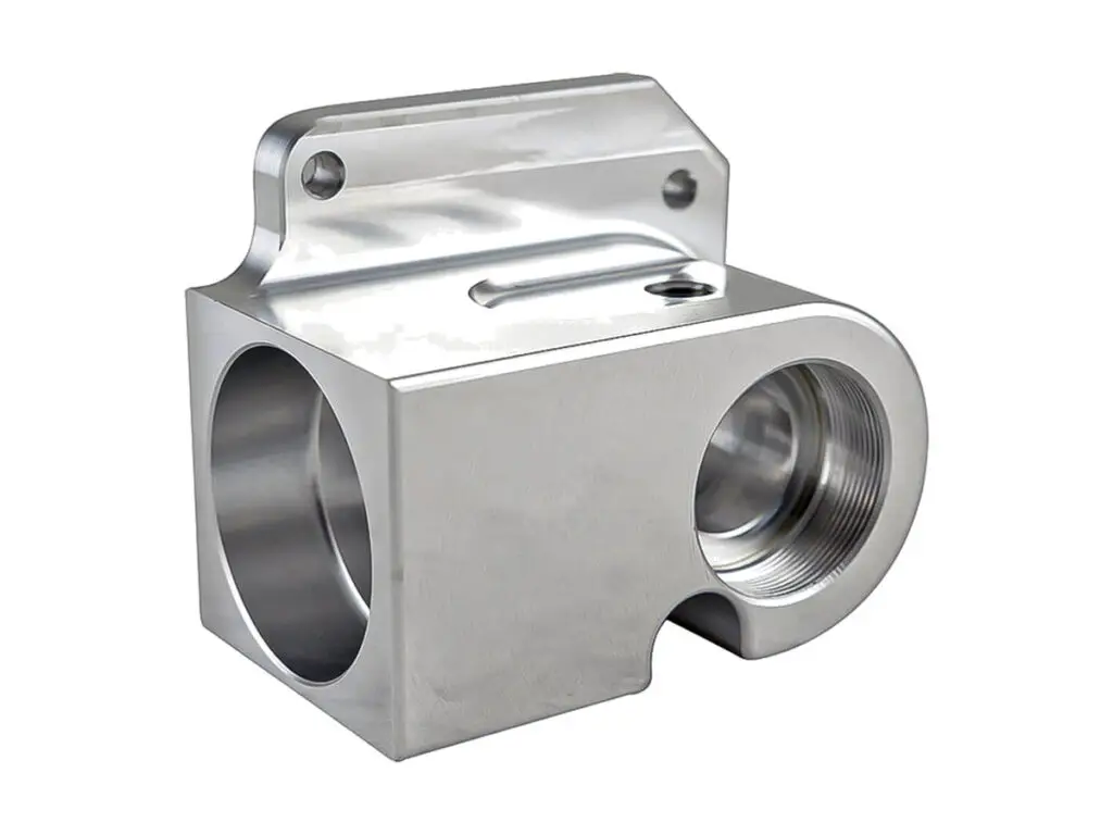
6061-T6 aluminium clevis blocks machined from solid with two parallel bores held to H7 and parallel within 0.02 mm, bore spacing to ±0.03 mm, a base flat to 0.02 mm and bore axes square to that base within 0.02 mm. Bores are masked before anodizing so pins still slide in by hand.
- Two Bores Parallel 0.02 mm
- Bores to H7
- Base Flat 0.02 mm
- Bore Axis Square to Base
*Send the pin diameters and the stroke. A twin-bore block is a linkage part, and the parallelism figure has to be tighter than the clearance in the pins or the mechanism will bind at the end of the stroke.
Twin-Bore Clevis Block Overview
Two bores in one block make a rigid pivot, which is useful until the bores are not parallel: then the pins fight each other and the linkage binds at one end of its travel. Parallelism, not size, is the number that decides whether it works.
The block is squared and the base is finished first, then both bores are cut in one set-up with a boring head, working from the base as the datum. Spacing is measured between bore walls with a pin and a micrometer rather than between centres, which is more accurate on the shop floor.
6061-T6 Aluminium Block
6061-T6 is used because a clevis block is usually a light pivot in an automation assembly, and the alloy holds a bored wall without the ringing that a thin steel block gives during boring.
7075-T6 or 304 Stainless
7075-T6 is chosen when the pins carry a reversing load and the bore walls must not ovalise. Stainless is used where the block sits in washdown or outdoor equipment and the bores must not corrode onto the pins.
Bore pressure and environment decide the alloy; the wall thickness then follows, at a minimum of 1.2 times the bore diameter to keep the bore round after boring.
Twin-Bore Clevis Block Specifications
Milling and boring data for clevis blocks, with the parallelism, spacing and squareness values that decide whether the linkage moves freely.
| Specification | Machining Data | Specification | Machining Data |
|---|---|---|---|
| Product | Twin-Bore Clevis Block / Pivot Block | Machining Process | 3-Axis CNC Milling, Boring, Line Reaming |
| Material | 6061-T6 Aluminium Block | Block Size | 50 × 40 × 30 to 250 × 150 × 90 mm |
| Bore Diameter | Ø 8 – 60 mm, H7 | Bore Parallelism | 0.02 mm |
| Bore Spacing | 30 – 200 mm, ±0.03 mm | Bore to Base Squareness | 0.02 mm |
| Base Flatness | 0.02 mm | Wall Around Bore | 1.2 × Bore Diameter Minimum |
| Surface Finish | Ra 1.6 µm Bores, Ra 3.2 µm Body | Anodizing | Type II 15 – 25 µm, Bores Masked |
| Customization | Cross Holes, Grease Nipples, Slot Between Bores, Mounting Flange | Lead Time | 6 – 8 Days Sample, 13 – 16 Days Batch |
| Inspection | Pin Through Both Bores, CMM Bore Spacing, Granite Flatness | Packing | Bore Plugs, Foam Cradle, Carton |
Key Features of Our Clevis Blocks
Bored from the base, spacing measured between walls.
Bores Cut From the Finished Base
Both bores are bored with the block sitting on its finished base, so the axes are square to the mounting face within 0.02 mm and the pins sit in the plane of the mechanism.
Parallelism to 0.02 mm
The two bores are cut in one set-up, so the pins stay parallel through the stroke instead of converging and loading the bushings at one end.
Spacing Measured Between Walls
Centre distance is controlled by measuring between bore walls with gauge pins, which removes the backlash a centre-to-centre measurement carries on the shop floor.
Bores Masked Before Coating
Plugs are fitted before anodizing and the bores re-gauged after, so a coated block still takes its pins by hand.
Block whose two pins have to stay parallel?
Surface Finishes for Clevis Blocks
The bores are fits, the base is a datum and the outside is cosmetic.
| Finish | Main Purpose | Finish | Main Purpose |
|---|---|---|---|
| Type II Anodizing | Corrosion protection on a visible pivot block | Hard Anodizing | Wear resistance in the bores |
| Masked Bores | Keeps both bores at H7 after coating | Bead Blasting | Matte body before dye |
| Laser Marking | Bore size and spacing on the base | Dry Film Lubricant | Bores that run without grease |
*Hard anodizing adds 25 to 50 µm and is brittle under a pin load, so bores are usually Type II coated and masked, or reamed after coating.
Put your CNC milling parts into production today
All information and uploads are secure and confidential.
Trusted for Precision CNC Machined Components
Supporting OEM projects with accurate machining, flexible production, and reliable component quality.
Trusted for Precision CNC Milling.
Machining Process for Clevis Blocks
Both bores are bored from the finished base in one set-up, so the pivot pins are parallel and the mechanism does not bind through its stroke.
01. Pivot and Stroke Review
Confirm the pin diameters, the stroke and the clearance in the linkage, and set the parallelism limit tighter than the pin clearance before machining.
02. Square and Face
Machine all six faces square, finish the base and mark it as datum A, since every bore and hole is called from the base rather than the block outline.
03. Rough Both Bores
Drill and rough bore both ends leaving 0.3 mm, keeping the block clamped in one position so the second bore does not shift the first.
04. Finish Bore and Check
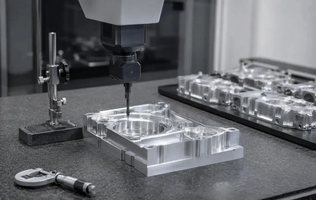
Finish bore both to H7, check parallelism with a pin through each, and measure spacing between bore walls before the block leaves the fixture.
05. Deburr, Mask and Anodize
Deburr the bore entries, plug the bores, anodize, pull the plugs and re-gauge both bores before packing each block in a foam cradle.
Send the pin and linkage drawings, and we will quote the block with both bores bored from the base and checked for parallelism.
Twin-Bore Clevis Block FAQs
0.02 mm over a block up to 200 mm. That is tighter than the clearance in a typical H7 pin fit, which is what stops the linkage binding at the end of the stroke.
Between bore walls with gauge pins and a micrometer, then confirmed on the CMM. Measuring centre to centre on the shop floor carries more error than the tolerance allows.
Yes, a slot or a lightening pocket between the bores is milled before boring so the walls stay supported during the cut, and it can double as a grease reservoir.
Yes, the bores are plugged and re-gauged. An unplugged bore closes by about 20 µm and a pin will not enter without a reamer.
At least 1.2 times the bore diameter for aluminium, more if the pin load reverses. Thinner walls bore oval and the pin then has a loose spot at 90°.
Yes, the bores can be sized for a press-fit bushing to your drawing. In that case the bore is finished after the block is anodized so the press fit is unaffected.
Other CNC Machined Mechanical Components
Explore additional precision CNC machined components manufactured for OEM applications and customized production needs.
Explore CNC milled UAV frames in 6061 or 7075 aluminum, built for lightweight structures, accurate assembly, component.
CNC machined 4140 alloy steel spur gears with hobbed teeth to DIN 6, bore and face square to 0.02 mm, induction hardened to 50.
Five-axis milled 316L stainless frame bases with compound-angle lightening windows, wall held to 1.5 mm and mounting faces flat.
Custom CNC machined aluminum gearbox housings with bored bearing seats and a split face.
Custom CNC machined aluminum motor bases and mounting pedestals for servo and spindle motors.
Get high‑quality machined parts in as fast as 4 days with our expanded automated CNC milling!