
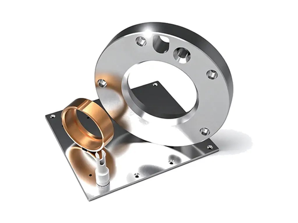


CNC Machined Aluminum Flanged Cylinder Housing
Flanged cylinder housings milled from 6061-T6 solid, with a bore from Ø30 to Ø120 mm held to H7 and round within 0.02 mm, a flange face square to the bore within 0.03 mm, a four-bolt circle at ±0.05 mm and a seal groove concentric to 0.04 mm. Each body is pressure tested at 1.5 times working pressure before anodizing.
- Bore H7, Round to 0.02 mm
- Flange Square to 0.03 mm
- Four-Bolt Circle ±0.05 mm
- Pressure Tested at 1.5×
*Send the piston or rod drawing and the working pressure. The bore clearance and the groove depth both follow the seal you use, and a groove 0.1 mm shallow will pinch the O-ring before the housing ever sees full pressure.
Flanged Cylinder Housing Overview
This housing holds a piston or a rod on a bore axis and bolts to a frame on a flange. Everything depends on those two features staying related: if the flange face is not square to the bore, the rod runs at an angle and the seal wears on one side.
The block is squared, the flange is faced, the bore is drilled, roughed and finished without unclamping, then the bolt circle and the ports are cut from the bore axis. The seal groove is cut with the boring bar still on the same centreline.
6061-T6 Aluminium
6061-T6 is the default for pneumatic and low-pressure hydraulic bodies: it machines to a stable bore, anodizes evenly and keeps the weight down where the housing is carried on a moving arm.
6082-T6 or 7075-T6
6082-T6 is used where the body is welded to a mounting plate, and 7075-T6 where the wall is thin and the ports sit close together, since it holds thread torque better in a 6 mm section.
A 6 mm wall is the minimum for a body above 1 MPa; below that the bore goes oval when the flange bolts are torqued, even if it gauged round on the bench.
Flanged Cylinder Housing Specifications
Boring, facing and drilling data for cylinder bodies, with the bore, flange and bolt values that keep a rod running true.
| Specification | Machining Data | Specification | Machining Data |
|---|---|---|---|
| Product | Flanged Cylinder Housing / Actuator Body | Machining Process | 3-Axis CNC Milling, Boring, Facing |
| Material | 6061-T6 Aluminium | Envelope | Bore Ø 30 – 120 mm, Length 40 – 260 mm |
| Bore | H7, Roundness 0.02 mm, Straightness 0.03 mm | Bore Finish | Ra 1.6 µm, Ra 0.8 µm on Request |
| Flange | Square 120 – 200 mm, Thickness 10 – 18 mm | Flange Face | Square to the Bore Within 0.03 mm |
| Bolt Circle | 4 or 8 Holes, ±0.05 mm | Counterbore | Depth ±0.05 mm, Flat Seat |
| Wall Section | 6 – 14 mm | Port Threads | G1/8 – G1/2, Square to the Bore 0.15 mm |
| Seal Groove | Width ±0.03 mm, Depth ±0.02 mm | Concentricity | 0.04 mm to the Bore |
| Customization | Port Positions, Drain Boss, Mounting Feet, Clevis End | Lead Time | 6 – 8 Days Sample, 12 – 18 Days Batch |
| Inspection | Bore Air Gauge, CMM Flange Squareness, Hydrostatic Test | Packing | Bore Plug, Foam Cradle, Sealed Bag |
Key Features of Our Cylinder Housings
One set-up for bore and flange, gauged and pressure tested before coating.
Bore and Flange From One Set-up
The flange is faced after the bore is finished, on the same clamping, so squareness stays within 0.03 mm and the body does not lean on its gasket under bolt load.
Groove Cut on the Bore Centreline
The seal groove is cut with the boring bar still in position, keeping concentricity at 0.04 mm so the O-ring is compressed evenly round its whole circumference.
Bolt Circle From the Bore Axis
Holes are positioned from the bore rather than the outside of the block, so a replacement body drops onto the existing frame without opening a hole.
Hydrostatic Test Before Anodizing
Each body is blanked and held at 1.5 times working pressure for 10 minutes while the surface is still bare, so a porous casting or a thin wall shows before coating hides it.
Cylinder body that has to run true?
Surface Finishes for Cylinder Housings
The bore is a fit, the flange is a joint face and the outside is a corrosion surface, so only the outside takes full coating.
| Finish | Main Purpose | Finish | Main Purpose |
|---|---|---|---|
| Clear Anodizing | Corrosion resistance with machined faces visible | Black Anodizing | Machine and automation finish |
| Masked Bore | Keeps the H7 sliding fit after coating | Hard Anodizing | Wear surface on a rod-less bore |
| Bead Blasting | Even matte on the flange and body | Chromate Conversion | Conductive body for earthed machines |
| Anodizing Build | 10 – 20 µm, Sealed | Laser Marking | Stroke and port identification |
| Bore Plug | Fitted Through Coating and Transit | Thread Masking | Ports stay at gauge size |
| Assembly Oil | Light film in the bore | Face Protection | Taped flange face for shipping |
*Anodizing grows 10 to 20 µm into an H7 bore and changes the running clearance. Bores are plugged, or left 40 µm undersize and finished after coating when the fit is critical.
Put your CNC milling parts into production today
All information and uploads are secure and confidential.
Trusted for Precision CNC Machined Components
Supporting OEM projects with accurate machining, flexible production, and reliable component quality.
Trusted for Precision CNC Milling.
Machining Process for Cylinder Housings
The bore and the flange face are machined in one clamping, so the housing sits square on its gasket instead of cocking on the bolt circle.
01. Rod and Seal Review
Check the rod diameter, the seal section and the working pressure, then set the bore tolerance and the groove depth from the seal datasheet.
02. Square and Face the Flange
Machine the block square and face the flange side first, because the bore, the groove and the bolt circle are all called from that face.
03. Rough and Finish the Bore
Drill, rough and finish bore to H7, gauging the diameter at three depths before the boring bar is withdrawn from the cut.
04. Cut Groove, Circle and Ports
Cut the seal groove in a single pass, drill and counterbore the bolt circle from the bore axis, then thread the ports square to the bore.
05. Test, Mask, Anodize
Pressure test at 1.5 times working pressure, plug the bore, anodize, then re-gauge the bore and cap the ports for packing.
Send the rod and seal drawing, and we will quote a housing with the bore, groove and flange cut from one datum and pressure tested before coating.
Flanged Cylinder Housing FAQs
H7 as standard, with roundness at 0.02 mm and straightness at 0.03 mm over the full length. A body that is 0.02 mm oval will show as a seal leak at one point on the circumference, not all round.
Yes. Groove width and depth are set from the seal datasheet, whether it is a metric O-ring, an imperial AS568 size or a lip seal, and the groove is cut with a form tool to that section.
Every body is pressure tested at 1.5 times working pressure for 10 minutes with the ports blanked. Vacuum bodies are tested at -90 kPa instead, because a leak inward does not show on a pressure test.
0.03 mm across the face, measured on a CMM with the bore as the datum. A flange 0.05 mm out will hold on the bolts but leak between them once the gasket takes a set.
Yes, on request the bore is left 40 µm undersize, the body is anodized and the bore is then finish bored. This is the usual route for a sliding fit or where the bore must stay conductive.
8 mm for a 60 mm bore at 1 MPa, and 12 mm where the body is also a structural mount. Thinner walls deflect under bolt preload and the bore goes oval before the body bursts.
Other CNC Machined Mechanical Components
Explore additional precision CNC machined components manufactured for OEM applications and customized production needs.
Five-axis CNC machined 7075-T6 aluminium wrist housings with compound-angle bores in one set-up, bores positioned to ±0.02 mm and.
CNC machined 6061-T6 aluminium flanged manifold housings with a H7 bore ground concentric to the flange, a machined seal groove.
CNC turned 6061-T6 aluminium bearing cover discs with a recessed spigot, a lapped sealing face and a bolt pattern, held to 0.02.
Five-axis CNC machined 6082-T6 aluminium manifold plates with cross-drilled galleries, spotfaced port faces and ports on five.
CNC machined 7075-T6 aluminium fork slider legs with a honed bore, machined axle slots and brake caliper lugs, held to ±0.03 mm.
Get high‑quality machined parts in as fast as 4 days with our expanded automated CNC milling!



