Home / CNC-Machining / CNC 5-Axis Machining / Five-Axis CNC Machined Aluminum Wrist Housing
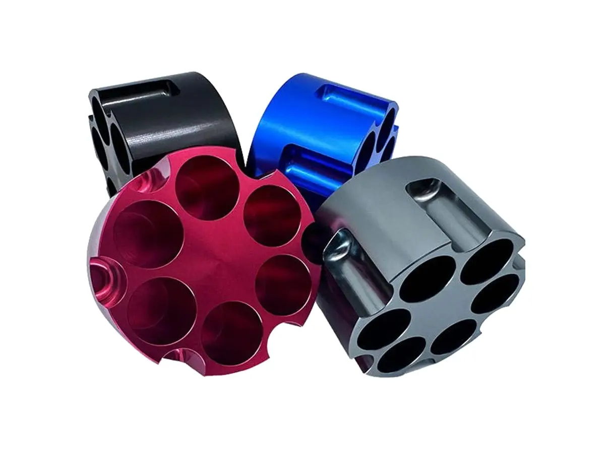
Five-axis CNC machined aluminum wrist housing with intersecting bearing bores

Five-Axis CNC Machined Aluminum Wrist Housing

Wrist housings machined on five axes from 7075-T6 billet, with compound-angle bores positioned to ±0.02 mm, bore axes angled to ±0.02°, 4 mm walls and coplanar mounting pads within 0.02 mm. Paired housings are matched in weight within 5 g.

*Send the kinematic model and the bearing drawing, not just a 2D print. The bore intersection point is what sets the robot repeatability, and a print usually dimensions each bore from a different face.

Wrist Housing Overview

A wrist housing carries two intersecting bearing bores at compound angles, and the distance between those axes is the robot accuracy. It cannot be machined in three axes without losing that relationship.

The billet is roughed on five axes leaving 1 mm, stress relieved, then finished in a single five-axis set-up so both bores, the pads and the motor flange stay in one coordinate system before the part is released.

Five-axis milling of an aluminum wrist housing for a robot arm
6061-T6 aluminium flat plate stock for CNC milling

7075-T6 Aluminium Billet

7075-T6 is used because the walls are 4 mm and the housing sees reversing loads at the wrist. Its strength lets the lightening pockets go deeper without the bore distorting under bearing preload.

7075-T6 aluminium billet block stock for CNC milling

6061-T6 or 6082-T6

6061 is chosen for a low-load wrist where cost matters more than stiffness, and 6082 where the housing is welded to a fabricated forearm instead of bolted.

Below 4 mm wall the bearing bore goes oval when the bearing is pressed in; the fix is a thicker wall or a steel insert, not a harder alloy.

Wrist Housing Specifications

Five-axis machining data for wrist housings, with the bore, angle and wall values that decide whether the arm repeats.

SpecificationMachining DataSpecificationMachining Data
ProductRobot Wrist Housing / Compound-Angle HousingMachining Process5-Axis Simultaneous CNC Milling, Boring
Material7075-T6 Aluminium BilletEnvelopeUp to 260 × 200 × 180 mm
Bore DiameterØ 30 – 110 mm, H7Bore Axis AngleAny Compound Angle, ±0.02°
Bore Position±0.02 mm in X, Y and ZBore Roundness0.015 mm
Wall Thickness4 – 10 mmWeb Thickness3 mm Minimum
Flange FaceSquare to Bore 0.02 mmMounting PadsCoplanar 0.02 mm
BalanceWithin 5 g Between Paired HousingsSurface FinishRa 1.6 µm Bores, Ra 3.2 µm Blends
CustomizationCable Passages, Motor Flange, Dowel Holes, Lightening PocketsLead Time8 – 10 Days Sample, 18 – 25 Days Batch
InspectionCMM Bore Axis and Position, Roundness, Pair WeighingPackingFoam Cradle per Housing, Pair Boxed

Key Features of Our Wrist Housings

Both axes cut in one set-up, roughed then stress relieved.

Both Bores in One Five-Axis Set-up

The wrist and forearm bores are finished without re-fixturing, so the axis intersection stays within 0.02 mm and the kinematic model matches the real arm.

Rough, Stress Relieve, Finish

The part is roughed to 1 mm, taken off the machine and stress relieved, then finished. Skipping that step moves the bores 0.03 mm overnight.

Walls Held at 4 mm

Wall thickness is checked with an ultrasonic gauge at six points after finishing, because a 3 mm wall goes oval under bearing preload and the wrist loses stiffness.

Pads Coplanar to 0.02 mm

The mounting pads are finished in the same set-up as the bores, so the housing bolts down without shims and the motor flange stays square to the axis.

Wrist housing that has to hold its axis?

Surface Finishes for Wrist Housings

Bores and pads are fits, the body is visible and the pockets are hard to coat evenly.

FinishMain PurposeFinishMain Purpose
Hard AnodizingWear resistance on the bore and padsType II AnodizingColour on the visible body
Masked BoresBores stay at H7 after coatingBead BlastingEven matte before dye
Laser MarkingAxis reference and serialChromate ConversionConductive finish for earthed arms
Anodizing Build25 – 50 µm on Wear FacesVapour BlastingSatin Blends Between Pockets
Bore PlugsRemoved After CoatingPad ProtectionTaped Coplanar Faces
Balance MarkDot on the Light SideAssembly CleanUltrasonic Before Bearing Fit

*Hard anodizing builds 25 to 50 µm and will take up the H7 bore. Bores are masked with expanding plugs and the pads are taped, otherwise the bearing will not go in and the pad will not sit flat.

logo

Put your CNC milling parts into production today

All information and uploads are secure and confidential.

Trusted for Precision CNC Machined Components

Supporting OEM projects with accurate machining, flexible production, and reliable component quality.

Mechanical Equipment Customer
Both bores lined up with the kinematic model, and the repeatability came back at the tool.

Industrial Components Buyer
The pads sat flat without shims, and the motor flange bolted square to the axis.

Equipment Manufacturer
No binding in either axis after a full season of running.

OEM Customer
OEM Customer
The pair weighed the same, so the left and right wrists tune the same.

Automation Industry Customer
The customized machining solution provided the dimensional accuracy required for our rotating equipment components.

Trusted for Precision CNC Milling.

Machining Process for Wrist Housings

Both bores are cut in one five-axis set-up, so the wrist axis and the forearm axis intersect where the kinematic model says they do.

01. Kinematics and Bearing Review

Check the axis intersection, the bearing fits and the motor flange, then build the five-axis model from those rather than from the 2D print.

02. Rough on Five Axes

Rough all faces and pockets leaving 1 mm, keeping the part on a dovetail so it can be turned over without losing the datum.

03. Stress Relieve

Take the part off, stress relieve it and let it settle, because 80 % of the material has been removed and the bores will move otherwise.

04. Finish Bores and Pads

Finish both bores, the pads and the motor flange in one five-axis set-up, checking the axis intersection on the CMM before unclamping.

05. Match, Anodize, Verify

Weigh and match the pair, mask the bores and pads, hard anodize, then re-check the bore size and the pad coplanarity.

Send the kinematic model and the bearing fits, and we will quote a wrist housing with both axes cut in one set-up.

Wrist Housing FAQs

Because the two bearing bores intersect at a compound angle. In three axes the part has to be re-fixtured between bores, and each re-fixture adds 0.02 to 0.04 mm to the axis intersection error.

0.02 mm in X, Y and Z, measured on the CMM with a mandrel in each bore. That is the number that shows up as repeatability at the tool centre point.

Yes, for any housing where more than 60 % of the billet is removed. Without it the bores move 0.03 mm in the first 24 hours and the part is scrap.

4 mm as standard and 3 mm in a local web. Below 3 mm the wall deflects under bearing preload and the bore goes oval even though it was round on the CMM.

By weight within 5 g and by bore position within 0.01 mm of each other, so a left and right wrist behave the same under the same servo tuning.

Yes, bores and pads are masked as standard. If a coated bore is needed it is machined undersize and honed after anodizing to the finished H7 size.

Other CNC Machined Mechanical Components

Explore additional precision CNC machined components manufactured for OEM applications and customized production needs.

Precision CNC machined aluminum robot joint housings for arm segments and joint modules.

Precision CNC machined aluminum robot joint housing flanges.

Custom CNC machined aluminum intake manifolds for automotive and motorsport builds.

Custom CNC machined stainless steel multi jaw clamping plates for lathe, grinder and wheel hub fixtures.

Custom CNC machined aluminium indexing disks for rotary positioning systems.

Get high‑quality machined parts in as fast as 4 days with our expanded automated CNC milling!

Scroll to Top