


Home / CNC-Machining / CNC 5-Axis Machining / Five-Axis CNC Machined Aluminum Manifold Plate
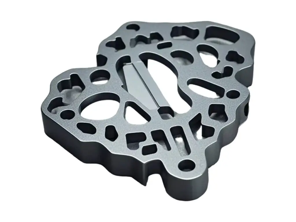
Five-axis machined aluminum manifold plate with ports on five faces

Five-Axis CNC Machined Aluminum Manifold Plate

Manifold plates five-axis machined from 6082-T6 plate, with cross-drilled galleries from Ø 4 to 16 mm, port faces spotfaced square to their axis within 0.05 mm, ports on five faces of the block and cartridge cavities machined in one set-up. Each plate is pressure tested at 1.5 times working pressure and the galleries are borescoped before the ports are plugged.

*Send the hydraulic schematic and the cartridge valve datasheets. The cavity depth, the gallery breakout position and the port angle all come from the valves, not from the block outline.

Manifold Plate Overview

A manifold replaces a bundle of pipes with holes in a block. Every gallery has to meet the right port at the right depth, every port face has to be square to its thread and every cavity has to be concentric, or a cartridge valve will leak or bind.

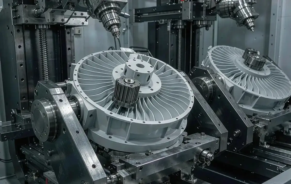
A five-axis machine is used because the ports sit on faces that are not all perpendicular. One datum serves every face, the deep galleries are drilled in a peck cycle with through-coolant, and each breakout is deburred from the inside before the next hole is drilled.

Five-axis machining of a vacuum pump impeller and a twin-body valve housing
6061-T6 aluminium flat plate stock for CNC milling

6082-T6 Aluminium Plate

6082-T6 is the standard manifold alloy in Europe: it machines fast, holds a thread well and anodizes evenly. Plate is used up to 120 mm thick because it is stress-relieved and stays flat after the galleries are drilled.

7075-T6 aluminium billet block stock for CNC milling

7075-T6 or Ductile Iron

7075-T6 is used where the working pressure is above 250 bar and the wall between galleries is thin. Ductile iron is specified for pressures above 350 bar, where aluminium would fatigue around the port threads.

The pressure rating decides the material, and the wall between galleries decides the block size. Below 3 mm of wall the block will weep between circuits, whatever the alloy.

Manifold Plate Specifications

Five-axis data for manifold blocks, with the gallery, port and cavity values that decide whether the circuit holds pressure.

SpecificationMachining DataSpecificationMachining Data
ProductManifold Plate / Distribution BlockMachining Process5-Axis CNC Milling, Deep Drilling, Tapping
Material6082-T6 Aluminium PlateEnvelopeUp to 400 × 300 × 120 mm
Gallery DiameterØ 4 – 16 mm, Position ±0.10 mmPort FaceSpotfaced Square 0.05 mm to the Port Axis
Port ThreadsG1/8 – G1/2, Cut to Pre-Plate SizePlate Flatness0.05 mm on the Mounting Face
Cross-drill BreakoutDeburred, No Step Inside the GalleryWall Between Galleries3 mm Minimum
Pressure Test1.5 × Working Pressure, 10 min HoldSurface FinishRa 1.6 µm on Port Faces
CustomizationCartridge Valve Cavities, Gauge Ports, Test PointsLead Time7 – 9 Days Sample, 14 – 18 Days Batch
InspectionCMM Port Position and Angle, Borescope Galleries, Leak Test RecordPackingPorts Plugged, VCI Wrap, Foam Crate

Key Features of Our Manifold Plates

One datum for five faces, every breakout deburred.

Ports on Five Faces From One Datum

Five-axis machining means the top, sides and ends all reference the same datum, so a gallery drilled from the top meets the side port within 0.10 mm.

Deep Galleries With Through-Coolant

Long galleries are drilled in a peck cycle with coolant through the tool, which stops the chips packing and keeps the hole straight.

Breakouts Deburred Inside

Each cross-drill breakout is deburred from the bore side, so no burr is left to travel into a valve or a cylinder.

Pressure Tested and Borescoped

Every block is borescoped for breakout quality and pressure tested at 1.5 times working pressure for ten minutes, with the record supplied.

Block that has to route pressure without leaking?

Surface Finishes for Manifold Plates

Port faces and cavities are fits; the outside is only corrosion protection and identification.

FinishMain PurposeFinishMain Purpose
Type II AnodizingCorrosion protection on external facesHard AnodizingWear resistance in cartridge cavities
Masked Port FacesKeeps port faces flat and threads at sizeBead BlastingMatte finish before dye
Chromate ConversionConductive body for an earth strapLaser MarkingPort identification and flow direction

*Anodizing closes a port thread and changes a cavity bore. Ports and cavities are masked with plugs, and threads are cut to a pre-plate size before coating.

logo

Put your CNC milling parts into production today

All information and uploads are secure and confidential.

Trusted for Precision CNC Machined Components

Supporting OEM projects with accurate machining, flexible production, and reliable component quality.

Mechanical Equipment Customer
Every port lined up with the pipework, and nothing needed re-bending at installation.

Industrial Components Buyer
No pressure drop across the block beyond the schematic, so the galleries are clean.

Equipment Manufacturer
Cartridge valves seated at the right depth and none needed a shim.

OEM Customer
OEM Customer
The port map they issued let us build the hoses before the blocks arrived.

Automation Industry Customer
The customized machining solution provided the dimensional accuracy required for our rotating equipment components.
Trusted for Precision CNC Milling.

Five-Axis Machining Process

Every port is machined from the same datum on a five-axis machine, so a gallery cannot miss the face it is supposed to break out of.

01. Schematic and Cavity Review

Map every gallery against the schematic, check the cartridge cavity depths and confirm which faces carry ports before programming.

02. Square and Face the Block

Machine all six faces square and flat to 0.05 mm, establishing the datum corner that every port and gallery will be measured from.

03. Drill the Galleries

Drill the long galleries in a peck cycle with through-coolant, then cross-drill the connecting holes and check the breakouts with a borescope.

04. Machine Port Faces and Cavities

Rotate the block on the trunnion to spotface each port square to its axis, then machine the cartridge cavities and cut the threads.

05. Deburr, Test, Plug

Deburr every breakout, wash the galleries, pressure test at 1.5 times working pressure, then plug the ports and crate the block.

Send the hydraulic schematic and the valve datasheets, and we will quote a manifold with every port on its true angle and pressure tested.

Manifold Plate FAQs

Because ports sit on faces that are not all square to each other. On a three-axis machine each face needs its own fixture and the angular error accumulates across the block; on a trunnion every port comes from one datum.

The gallery position is held to ±0.10 mm, which puts the breakout inside a port bore of Ø 4 mm or larger. Smaller ports are drilled from the port side to keep the breakout centred.

Yes, from the valve datasheet, with the cavity diameter, depth and chamfer held to the valve maker's tolerance. Cavities are checked with a plug gauge and a depth micrometer.

1.5 times working pressure for ten minutes as standard. Blocks for 350 bar service are made in steel or iron, not aluminium.

High-pressure wash, then a borescope inspection of every breakout, then plugs fitted. Blocks are shipped with the ports plugged so no swarf enters in transit.

Yes, but a schematic is better. The drawing shows where the holes go; the schematic shows which circuits must connect, and that is what the machining programme is built from.

Other CNC Machined Mechanical Components

Explore additional precision CNC machined components manufactured for OEM applications and customized production needs.

Custom CNC machined aluminum hollow L brackets with lightening cut-outs, machined in 6061-T6 or 7075-T6, flat to 0.05 mm and anodized to your colour.

Custom CNC machined aluminium motorcycle components, including clamps, covers, mounts and bearing housings.

Custom CNC machined aluminium filament stand brackets for 3D printer spool holders.

Custom CNC machining milling aluminum robot base frames for industrial robots and automation equipment.

Custom Bearing Housing CNC Milled components manufactured with precision CNC machining, supporting OEM customization, prototypes,.

Get high‑quality machined parts in as fast as 4 days with our expanded automated CNC milling!

Scroll to Top