


Home / CNC-Machining / CNC Milling / CNC Machined Stainless Steel Disc Hub Set
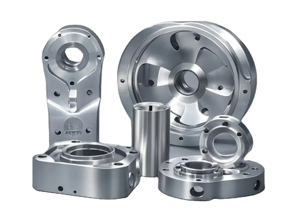
CNC machined stainless steel disc hub with a bored H7 centre, milled lightening pockets and a reamed bolt circle

CNC Machined Stainless Steel Disc Hub Set

Disc hubs and split clamp rings machined from 304 stainless, with a H7 bore coaxial to the bolt circle within 0.02 mm, a bolt circle at ±0.03 mm, face runout under 0.02 mm and lightening pockets matched within 2 g so the pair balances without weights.

*Give us the shaft fit and the torque you run through the disc. A hub bored H7 on a worn shaft will move 0.03 mm under load, which shows up as a wobble at the rim that no amount of re-tightening fixes.

Stainless Disc Hub Overview

A disc hub carries torque between a shaft and a disc, and it does that through two features only: the bore fit and the bolt circle. Everything else on the part is there to keep those two from moving.

The disc is turned on both faces, the bore is bored with a single-point bar, the bolt circle is interpolated from the bore centre, and the lightening pockets are milled in a mirrored pattern so the part does not need balancing afterwards.

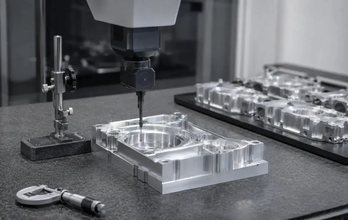
CMM inspection of a gripper jaw set, a brass manifold block and an eight-lobe flange plate
304L stainless steel round bar stock for CNC machining

304 Stainless

304 is used where the disc sees washdown or food contact: it does not need coating, and passivation after machining removes the free iron that would otherwise show as rust spots around the bolt holes.

304L stainless steel plate and block stock for CNC machining

17-4 PH or 316L

17-4 PH in the H1150 condition is chosen when the hub is keyed to a shaft and takes shock torque, and 316L where chlorides are present, at the cost of a softer bore that wears faster on a sliding fit.

A 12 mm disc is the practical minimum under a 260 mm hub; below that the face deflects during boring and the runout comes back after the part is unclamped.

Disc Hub Specifications

Boring and circle data for stainless hubs, with the coaxiality and runout values that keep a disc true at speed.

SpecificationMachining DataSpecificationMachining Data
ProductDisc Hub and Clamp Ring SetMachining ProcessCNC Milling, Boring, Face Turning
Material304 Stainless, 17-4 PH on RequestEnvelopeØ 120 – 260 mm, 12 – 30 mm Thick
BoreH7, Roundness 0.015 mmBore Coaxiality0.02 mm to the Bolt Circle
Bolt Circle4 – 12 Holes, ±0.03 mmHole SizeØ 6.6 / 8.4 / 10.5 mm, Drilled and Reamed
Face Runout0.02 mm at the RimFace Flatness0.015 mm Across the Hub
Lightening PocketsDepth ±0.05 mm, Floor Ra 3.2 µmBalancePockets Matched Within 2 g
Clamp RingSplit 4 mm, Two M6 Clamp ScrewsRing GapParallel Within 0.05 mm
CustomizationKeyway, Taper Bore, Dowel Pattern, Balance HolesLead Time6 – 8 Days Sample, 14 – 18 Days Batch
InspectionCMM Bolt Circle, Granite Face Check, Bore Air GaugePackingHub Cap, VCI Bag, Crate

Key Features of Our Disc Hubs

Bored, not reamed; circle interpolated from the bore; pockets balanced in pairs.

Bore Bored in One Pass

Reaming a 60 mm bore follows the pre-drilled hole, so the bore is single-point bored from the same clamping as the faces and stays within 0.015 mm of round.

Bolt Circle From the Bore

The circle is interpolated about the bored centre rather than from the outside diameter, which is what stops the disc from being pulled off centre when the screws are torqued in sequence.

Pockets Mirrored in Pairs

Lightening pockets are cut in a mirror pattern about the axis, so the imbalance left after milling stays under 2 g and the hub does not need a balance pass.

Split Ring Cut After Boring

The clamp ring is bored first and split afterwards with a 4 mm slitting saw, so the two halves close on the shaft without a step at the split line.

Disc that has to run true at speed?

Surface Finishes for Disc Hubs

Contact faces stay bare, the rim can be finished to match the machine.

FinishMain PurposeFinishMain Purpose
PassivationRemoves free iron after machiningBead BlastingEven matte on non-contact faces
ElectropolishingRa 0.4 µm on a hygienic discMirror PolishDecorative visible face
Masked BoreKeeps the H7 fit after passivationBlack OxideNon-stainless variant only
Laser MarkingBolt circle and balance positionEdge Break0.4 mm on both rim edges
Bore PlugFitted for transitFace ProtectionPeel film on the lapped face
Salt Spray500 h on 304 after passivationRoundness RecheckMeasured After Passivation

*Electropolishing removes 5 to 8 µm and slightly opens the bore; on a H7 fit the bore is masked or bored 0.01 mm under before polishing.

logo

Put your CNC milling parts into production today

All information and uploads are secure and confidential.

Trusted for Precision CNC Machined Components

Supporting OEM projects with accurate machining, flexible production, and reliable component quality.

Mechanical Equipment Customer
The disc runs true on the shaft with no wobble at the rim.

Industrial Components Buyer
The bolt pattern matched the old hub, so we did not have to re-drill the coupling.

Equipment Manufacturer
The split ring closed evenly on the shaft without a step at the split.

OEM Customer
OEM Customer
Both halves weighed the same, so the assembly needed no balancing.

Automation Industry Customer
The customized machining solution provided the dimensional accuracy required for our rotating equipment components.

Trusted for Precision CNC Milling.

Machining Sequence for a Disc Hub

The bore is bored in the same clamping as the bolt circle, so the disc runs true on the shaft instead of being pulled off centre by the screws.

01. Fit and Pattern Review

Confirm the shaft tolerance, the torque direction and the bolt pattern, and decide whether the bore runs H7 or a light press.

02. Turn Both Faces

Hold on the outside diameter in soft jaws, turn both faces and the rim in one operation, leaving 0.2 mm on each face for the finish pass.

03. Bore and Check Coaxiality

Bore with a single-point bar, measure roundness in two planes, then interpolate the bolt circle from the same centre without unclamping.

04. Mill Pockets and Split

Cut the lightening pockets in a mirrored pattern, drill the clamp screw holes, then split the ring with a slitting saw and deburr both cut faces.

05. Passivate and Protect

Passivate, rinse and dry, plug the bore, apply peel film to the lapped face and pack with the hub cap fitted.

Send the shaft diameter and the bolt pattern, and we will quote a hub bored and circled in one set-up, with the runout measured before packing.

Disc Hub FAQs

A reamer follows the drilled hole, so on a 60 mm bore the error from the drill stays in the part. Boring corrects position and roundness in the same pass and holds 0.015 mm.

Yes, from a drawing or a sample hub. We measure the pattern on a CMM and cut to the measured centre rather than the nominal, which keeps a replacement disc interchangeable with the old one.

Under 2 g on a 200 mm hub with mirrored pockets. Above that the part is balanced on a mandrel and corrected with drilled holes between the bolt holes.

It removes a few micrometres of free iron but does not change the dimension. Electropolishing does, by 5 to 8 µm, so the bore is masked when the fit is critical.

4 mm for a 200 mm ring, 3 mm below 120 mm. A narrower split will close before the ring grips the shaft, and a wider one leaves the ring oval after clamping.

Yes, and it is the usual way: the disc is faced against the hub face, so the pair is machined and marked together and the runout is checked assembled.

Other CNC Machined Mechanical Components

Explore additional precision CNC machined components manufactured for OEM applications and customized production needs.

Five-axis CNC machined 7075-T6 aluminium wrist housings with compound-angle bores in one set-up, bores positioned to ±0.02 mm and.

CNC machined 6061-T6 aluminium flanged manifold housings with a H7 bore ground concentric to the flange, a machined seal groove.

CNC turned 6061-T6 aluminium bearing cover discs with a recessed spigot, a lapped sealing face and a bolt pattern, held to 0.02.

Five-axis CNC machined 6082-T6 aluminium manifold plates with cross-drilled galleries, spotfaced port faces and ports on five.

CNC machined 7075-T6 aluminium fork slider legs with a honed bore, machined axle slots and brake caliper lugs, held to ±0.03 mm.

Get high‑quality machined parts in as fast as 4 days with our expanded automated CNC milling!

Scroll to Top