

Home / CNC-Machining / CNC-Turning / CNC Turned Aluminum Bearing Cover Discs
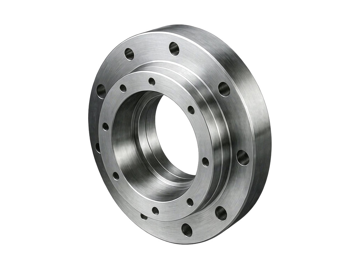
CNC turned aluminum bearing cover discs with a lapped sealing face

CNC Turned Aluminum Bearing Cover Discs

Bearing cover discs turned from 6061-T6 bar, with a spigot held to H8 and 0.015 mm roundness, a sealing face lapped flat to 0.01 mm, a bolt circle positioned to ±0.05 mm and a recess depth held to ±0.05 mm. Discs are supplied in pairs matched to 0.03 mm in thickness so a shaft is covered evenly at both ends.

*Send the housing bore and the bearing outer diameter. The spigot is cut to the housing, and a disc turned to nominal will either be loose or need to be pressed in.

Bearing Cover Disc Overview

A cover disc closes a bearing housing and holds the outer race in place. Its spigot centres it, its face seals it and its bolt circle clamps it. If the spigot and the face are not machined together, the disc cocks and the seal weeps at one side.

The disc is turned from bar in one operation: face, spigot, recess and outside diameter, then the bolt circle is drilled from the same centre. The sealing face is lapped after turning and the part is checked on granite before anodizing.

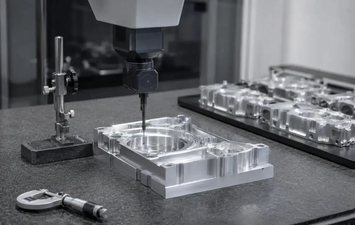
CMM inspection of a gripper jaw set, a brass manifold block and an eight-lobe flange plate
6061-T6 aluminium round bar stock for CNC turning

6061-T6 Aluminium Bar

6061-T6 is used for covers on aluminium housings because the two expand at the same rate, so the spigot fit does not change when the gearbox warms up. It also anodizes to a predictable thickness on the spigot when masked.

7075-T6 aluminium round disc blank for CNC machining

6082-T6 or Steel

6082 is the European equivalent and is used where the certificate must match a standard. Steel covers are specified where the disc also retains a bearing preload spring and the bolt threads must not pull out of aluminium.

Match the cover to the housing material wherever the operating temperature swings; a steel cover in an aluminium housing loosens its spigot when hot.

Bearing Cover Disc Specifications

Turning data for cover discs, with the spigot, face and bolt values that decide whether the bearing stays covered and dry.

SpecificationMachining DataSpecificationMachining Data
ProductBearing Cover Disc / End Cap DiscMachining ProcessCNC Turning, Facing, Drilling
Material6061-T6 Aluminium BarDiameter RangeØ 50 – 320 mm
Spigot DiameterØ 30 – 280 mm, H8, Roundness 0.015 mmSealing FaceFlatness 0.01 mm, Ra 0.8 µm
Disc Thickness6 – 30 mmBolt Circle4 – 12 Holes, Position ±0.05 mm
ConcentricitySpigot to Bolt Circle 0.03 mmRecess Depth±0.05 mm
Surface FinishRa 1.6 µm Faces, Ra 0.8 µm SpigotPair MatchThickness Within 0.03 mm
CustomizationGrease Nipple, Sight Glass, Sensor BossLead Time5 – 7 Days Sample, 10 – 14 Days Batch
InspectionCMM Spigot and Bolt Circle, Granite Flatness, Pair ThicknessPackingFace Protected, Pair Boxed, Foam Separators

Key Features of Our Cover Discs

Spigot, face and bolt circle from one centre.

Spigot and Face in One Operation

The spigot and the sealing face are turned without reclamping, so the face runs square to the spigot and the disc does not cock when bolted.

Sealing Face Lapped

Lapping brings the face to 0.01 mm flatness and removes the turning mark that a gasket or O-ring would otherwise follow and leak along.

Bolt Circle From the Spigot Centre

Holes are drilled from the spigot centre to ±0.05 mm, so the disc drops onto the studs without opening the holes or stressing the face.

Pairs Matched in Thickness

Discs for both ends of a shaft are measured together and finished within 0.03 mm, keeping the bearing preload symmetrical.

Cover that has to seal a bearing housing?

Surface Finishes for Cover Discs

The spigot and face are fits; the outside face is visible and only needs corrosion protection.

FinishMain PurposeFinishMain Purpose
Type II AnodizingCorrosion protection and colour on the visible discHard AnodizingWear resistance where a seal lip runs
Masked SpigotKeeps the spigot fit at H8Bead BlastingEven matte before dye
Laser MarkingBearing size and rotation directionBare Sealing FaceKeeps the lapped face flat and uncoated

*Anodizing adds 5 to 10 µm and will close a H8 spigot. Spigots are masked, and the sealing face is always left bare so the lapped flatness is preserved.

logo

Put your CNC milling parts into production today

All information and uploads are secure and confidential.

Trusted for Precision CNC Machined Components

Supporting OEM projects with accurate machining, flexible production, and reliable component quality.

Mechanical Equipment Customer
The discs sat square in the housing, and the seal has not wept since fitting.

Industrial Components Buyer
The pair matched in thickness, so the bearing preload is even at both ends.

Equipment Manufacturer
The bolt circle lined up, and no holes had to be opened out.

OEM Customer
OEM Customer
The sealing face was flat, so the gasket sealed without compound.

Automation Industry Customer
The customized machining solution provided the dimensional accuracy required for our rotating equipment components.

Trusted for Precision CNC Milling.

Turning Process for Cover Discs

The spigot and the sealing face are turned in one operation, so the disc seats square in the housing instead of being pulled in by the bolts.

01. Housing and Bearing Review

Check the housing bore, the bearing outer diameter and the bolt pattern, and confirm whether the disc carries a seal or only a cover.

02. Turn Face and Spigot

Face the disc, turn the spigot to H8 and cut the recess in one operation, checking the spigot with a micrometer before parting off.

03. Drill the Bolt Circle

Drill the bolt circle from the spigot centre, counterbore where specified and deburr both faces of every hole.

04. Lap the Sealing Face

Lap the sealing face flat to 0.01 mm, check it on a surface plate with light behind a straight edge, then clean the part.

05. Mask, Anodize, Check

Mask the spigot and the sealing face, anodize, then CMM the bolt circle and re-check the spigot diameter after coating.

Send the housing bore and the bearing drawing, and we will quote discs with the spigot and face machined together.

Bearing Cover Disc FAQs

H8 in the housing bore gives a light push fit that still centres the disc. A tighter fit needs the housing measured, because a disc turned to nominal will not enter a bore at the low limit.

A turned face has a spiral feed mark that runs from the inside to the outside, which is a leak path under a gasket. Lapping crosses the mark and brings flatness to 0.01 mm.

By about 10 µm, which is enough to make an H8 fit tight. Spigots are masked, and the sealing face is left bare so the lapped surface is not disturbed.

Yes, a tapped boss or a drilled and tapped hole is added before lapping, positioned so the nipple clears the rotating parts inside the housing.

Both discs are turned from the same bar and measured together, then finished to within 0.03 mm in thickness. The pair is boxed together with the match number.

320 mm diameter, which covers most bearing housings up to a 280 mm spigot. Larger covers are machined as a ring and a plate, bolted and sealed.

Other CNC Machined Mechanical Components

Explore additional precision CNC machined components manufactured for OEM applications and customized production needs.

Custom CNC machining milling aluminum robot base frames for industrial robots and automation equipment.

Custom Bearing Housing CNC Milled components manufactured with precision CNC machining, supporting OEM customization, prototypes,.

CNC milled aluminium robot joint adapter plates with a turned register, bolt circle to ±0.02 mm, flatness 0.02 mm and red.

Precision CNC machined steel locating flanges for robot joints.

Precision CNC machined aluminum multi hole fixture plates with a lapped grid of locating holes.

Get high‑quality machined parts in as fast as 4 days with our expanded automated CNC milling!

Scroll to Top