


Home / CNC-Machining / CNC-Turning / CNC Turned Stainless Steel Flanged Spindle
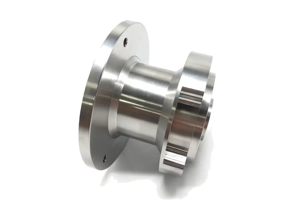
CNC turned stainless steel flanged spindle with ground journals

CNC Turned Stainless Steel Flanged Spindle

Flanged spindles turned and ground from 17-4PH stainless in the H900 condition, with bearing journals held to 0.005 mm and 0.003 mm roundness, a flange face square to the axis within 0.01 mm, a nose thread cut to 6g and residual unbalance within G6.3 at 4,000 rpm. Journals are concentric to the flange outside diameter within 0.01 mm.

*Send the bearing and tool-holder drawings. The journal size, the flange register and the nose thread are all set by the parts on either end, and a spindle made to its own drawing will not assemble.

Flanged Spindle Overview

A flanged spindle carries a tool or a chuck on a flange and runs in bearings on ground journals. Its accuracy comes from two relationships: journals to each other, and flange face to the journals. Both have to be ground, not turned.

The spindle is turned with grinding allowance, heat treated, then ground between centres so the journals share one axis. The flange face is ground square to that axis, the nose thread is cut after grinding, and the assembly is balanced before shipping.

Workshop production of a stainless steel stepped axle pin
304L stainless steel round bar stock for CNC machining

17-4PH Stainless, H900

17-4PH is used because it reaches high strength with a single low-temperature treatment, which keeps distortion small enough for a spindle. It also resists corrosion from coolant, which is what a spindle sees every day.

304L stainless steel plate and block stock for CNC machining

42CrMo4 or 440C

42CrMo4 is the choice for high-load machine tool spindles, through-hardened and ground, where corrosion is controlled by the coolant. 440C is used where both hardness and corrosion resistance are needed, at a higher material and grinding cost.

For a spindle running above 6,000 rpm the balance and the journal roundness matter more than the alloy; for a spindle in a wet environment the alloy decides the life.

Flanged Spindle Specifications

Turning and grinding data for flanged spindles, with the journal, flange and balance values that decide whether the tool runs true.

SpecificationMachining DataSpecificationMachining Data
ProductFlanged Spindle / Bearing Spindle ShaftMachining ProcessCNC Turning, Grinding, Thread Milling
Material17-4PH Stainless (H900)Length120 – 600 mm
Journal DiameterØ 15 – 80 mm, Ground to 0.005 mmRoundness0.003 mm on Journals
Flange DiameterØ 60 – 260 mmFlange Face Squareness0.01 mm to the Axis
Nose ThreadM20 – M64 or UN, 6g, GaugedConcentricityJournal to Flange OD 0.01 mm
Surface FinishRa 0.4 µm Journals, Ra 1.6 µm Flange FaceBalanceG6.3 at 4,000 rpm
CustomizationDrive Key, Draw Bar Thread, Tooling TaperLead Time9 – 12 Days Sample, 18 – 24 Days Batch
InspectionAir Gauge Journals, CMM Flange Squareness, Thread Gauges, Balance ReportPackingJournal Protection, VCI Wrap, Timber Case

Key Features of Our Flanged Spindles

Ground between centres, flange faced square.

Journals Ground From One Centre

Both journals are ground from the same centres, so they share an axis and the spindle does not preload one bearing against the other.

Flange Face Ground Square

The face is ground square to the journal axis within 0.01 mm, which is what stops a chuck or a tool holder from running out at the rim.

Nose Thread Cut After Grinding

Grinding is finished before the thread is cut, so no wheel mark or grit is left in the thread and the gauge fit is clean.

Balanced as an Assembly

Each spindle is balanced after grinding and the correction is made in the flange web, not the journals, so the bearing surfaces stay untouched.

Spindle that has to run true at speed?

Surface Finishes for Flanged Spindles

Journals and threads are fits; the flange face is a locating surface; the rest is corrosion protection.

FinishMain PurposeFinishMain Purpose
PassivationRemoves free iron after grindingHard ChromeWear resistance on a seal journal
Masked ThreadsKeeps the nose thread at gauge sizeElectropolishingLowers Ra on visible stainless faces
Oil CoatingCorrosion protection in transitLaser MarkingSerial and balance position

*Hard chrome adds 10 to 25 µm and is applied before the finish grind. Threads and the flange face are masked so the fits and the squareness are not changed.

logo

Put your CNC milling parts into production today

All information and uploads are secure and confidential.

Trusted for Precision CNC Machined Components

Supporting OEM projects with accurate machining, flexible production, and reliable component quality.

Mechanical Equipment Customer
The spindle runs true, and the tool holder indicates within what we need.

Industrial Components Buyer
Journals were on size, so the bearings went on with the specified fit.

Equipment Manufacturer
The flange face was square, and the chuck runs out less than before.

OEM Customer
OEM Customer
Balance was good at speed, with no vibration through the headstock.

Automation Industry Customer
The customized machining solution provided the dimensional accuracy required for our rotating equipment components.

Trusted for Precision CNC Milling.

Turning and Grinding Process

The journals and the flange face are ground from the same centres, so the tool that mounts on the flange runs true to the bearings that carry it.

01. Bearing and Tool Review

Check the bearing bores, the flange register and the nose thread, and confirm the heat treatment condition before rough turning.

02. Rough Turn and Treat

Rough turn with 0.4 mm of grinding allowance, leave the flange oversize and treat to H900 before any finish operation.

03. Grind the Journals

Grind both journals between centres, checking roundness and taper at both ends, and keep the part on the same centres for the flange face.

04. Grind Flange and Cut Thread

Grind the flange face square to the axis, then cut the nose thread and check it with a Go/No-Go gauge before balancing.

05. Balance, Mark, Pack

Balance the spindle, correct in the flange web, mark the balance position, then protect the journals and pack in a timber case.

Send the bearing and tool-holder drawings, and we will quote a spindle with the journals ground and the flange face square to 0.01 mm.

Flanged Spindle FAQs

A turned journal cannot hold 0.005 mm reliably and leaves a feed mark that a bearing race follows. Grinding gives the size, the roundness and the finish that a precision bearing needs.

0.01 mm to the journal axis, ground on the same centres. That is what keeps a chuck from running out at the rim, where the error is multiplied by the diameter.

Yes, from a drawing or a measured sample. The journals, the flange register and the thread are all measured, and the replacement is machined to the same fits.

17-4PH at H900 moves 0.1 to 0.3 mm depending on section, which is why the part is roughed oversize and finished after treatment. Larger spindles get a stress relief before roughing.

G6.3 at 4,000 rpm, measured on the finished spindle. Higher speeds need the spindle balanced with the chuck or tool holder fitted.

Yes, a draw bar thread is cut concentric to the nose thread, and the through bore is drilled before grinding so the grinding wheel does not break into it.

Other CNC Machined Mechanical Components

Explore additional precision CNC machined components manufactured for OEM applications and customized production needs.

Custom Brake Lever CNC Milled components manufactured with precision CNC machining, supporting OEM customization, lightweight.

CNC machined aluminium robot mounting brackets supplied as matched pairs, right-angle held to 0.05 mm, gusseted for stiffness and.

316L stainless multi-port valve bodies machined from solid, port faces flat to 0.02 mm and cross-drilled galleries pressure.

Custom five-axis CNC milled 316L stainless steel mixing impellers for agitators and reactors.

Precision CNC machined stainless steel control valve bodies with lapped sealing faces and gauged ports.

Get high‑quality machined parts in as fast as 4 days with our expanded automated CNC milling!

Scroll to Top