Home / CNC-Machining / CNC-Turning / CNC Turned Steel Stepped Drive Shafts
CNC turned and ground steel stepped drive shafts with h6 journals and milled keyways

CNC Turned Steel Stepped Drive Shafts

Stepped drive shafts turned from 1045 steel, with journals ground to h6 and round within 0.005 mm at Ra 0.4 µm, shoulders square to the axis within 0.02 mm, step-to-step concentricity of 0.01 mm and a runout of 0.015 mm checked between centres.

*Send the bearing part numbers and the step layout. A journal ground to the bottom of h6 on a bearing that sits at the top of its bore gives 0.02 mm of play, which is enough to hear at 3000 rpm.

Stepped Drive Shaft Overview

A stepped shaft carries torque through a keyway and locates a bearing on each journal. The journals have to be concentric to each other, or the bearing outer ring runs out and the housing wears oval.

The shaft is turned between centres leaving 0.3 mm on each journal, heat treated, straightened, then ground on the same centres so every diameter shares one axis.

CNC turning of a brass threaded flange bushing, an aluminum bearing sleeve and a retaining cover disc
304L stainless steel round bar stock for CNC machining

1045 Carbon Steel

1045 takes an induction-hardened case at the journal and still machines a straight shaft. It is the default for general drive shafts where the load is steady and the speed is under 4000 rpm.

304L stainless steel plate and block stock for CNC machining

4140 or 420 Stainless

4140 is used where the shaft takes shock load through a keyway, and 420 stainless where the shaft runs in washdown and a black oxide coating would break down in a season.

Straightening after heat treatment is not optional: a 500 mm shaft in 1045 typically bows 0.15 mm out of the furnace, and grinding a bowed shaft gives journals that are on size but not concentric.

Stepped Shaft Specifications

Turning, grinding and keyway data for drive shafts, with the runout and concentricity values that keep bearings quiet.

SpecificationMachining DataSpecificationMachining Data
ProductStepped Drive ShaftMachining ProcessCNC Turning, Cylindrical Grinding, Keyway Milling
Material1045 Carbon Steel, 4140 on RequestEnvelopeØ 8 – 60 mm, 80 – 600 mm Long
Journalsh6, Roundness 0.005 mmJournal FinishRa 0.4 µm Ground
ShouldersSquare to the Axis Within 0.02 mmRunout0.015 mm Between Centres
StepsDiameter ±0.02 mm, Length ±0.10 mmConcentricity0.01 mm Step to Step
KeywayWidth +0.02 / 0 mm, Depth ±0.05 mmThreadsM8 – M24, 6g, Rolled
HardnessHRC 28 – 32 on RequestStraightness0.02 mm per 300 mm
CustomizationStep Layout, Keyway, Snap Ring Groove, Thread, ChamferLead Time6 – 8 Days Sample, 14 – 18 Days Batch
InspectionMicrometer at Three Planes, Runout on Centres, Keyway GaugePackingJournal Wrap, VCI Paper, Tube

Key Features of Our Stepped Shafts

Ground between centres after heat treat, keyway after grinding, journals protected in transit.

Ground on One Axis

All journals are ground in one set-up between centres, so step-to-step concentricity stays at 0.01 mm instead of being built up from separate turning operations.

Shoulders Faced Square

Each shoulder is faced square to the axis within 0.02 mm, which is what stops a bearing inner ring from cocking when it is pressed up against the step.

Keyway Cut After Grinding

The keyway is milled after the journals are ground, so the broach does not raise a burr on a finished journal and the key does not sit proud on a hard surface.

Heat Treated Then Straightened

Shafts are induction hardened and straightened on a press before grinding, because grinding a bowed shaft produces a part that measures on size but runs out at the bearing.

Shaft that has to run quiet at speed?

Finishes for Stepped Shafts

Journals stay bare, the rest can be coated for corrosion.

FinishMain PurposeFinishMain Purpose
Black OxideRust protection with the journal maskedElectroless NickelUniform 15 µm on all steps
Hard ChromeWear surface on a sliding journalPhosphateKeyway and thread break-in
Masked JournalGrinding size kept after coatingRust Preventive OilFilm for transit
Induction HardeningHRC 50 at the bearing journalStress ReliefBefore finish grinding
Journal WrapProtects Ra 0.4 µm in packingVCI PaperPrevents condensation rust
Salt Spray96 h on Black OxideJournal RecheckSize After Coating

*Hard chrome adds 10 to 20 µm per side and must be ground back at the journal; on a h6 fit the journal is ground 0.02 mm under and chromed to size.

logo

Put your CNC milling parts into production today

All information and uploads are secure and confidential.

Trusted for Precision CNC Machined Components

Supporting OEM projects with accurate machining, flexible production, and reliable component quality.

Mechanical Equipment Customer
The bearings pressed on square and run quiet at full speed.

Industrial Components Buyer
The runout was inside 0.02 mm on our own check, exactly as the sheet said.

Equipment Manufacturer
The keyways were on size, so the pulleys went on without a file.

OEM Customer
OEM Customer
Five shafts in the batch and every journal measured the same.

Automation Industry Customer
The customized machining solution provided the dimensional accuracy required for our rotating equipment components.
Trusted for Precision CNC Milling.

Machining a Stepped Shaft

Every journal is ground after heat treatment, so the shaft stays straight and the bearing fit does not close up when the part cools.

01. Fit and Step Review

Confirm each bearing fit, the keyway size and the torque direction, then set the step diameters and the order of grinding.

02. Turn Between Centres

Face and centre both ends, rough and finish the steps between centres leaving 0.3 mm on each journal for grinding.

03. Heat Treat and Straighten

Induction harden the journals, temper, then straighten on a press to within 0.05 mm before the finish grind.

04. Grind and Cut Keyway

Grind every journal in one set-up between centres, check roundness in two planes, then mill the keyway and cut the snap ring grooves.

05. Check, Protect, Pack

Measure runout on centres, wrap each journal, apply rust preventive, and pack in a tube with VCI paper.

Send the bearing part numbers and the step drawing, and we will quote a shaft ground between centres with the runout recorded on the inspection sheet.

Stepped Drive Shaft FAQs

Turning holds about 0.02 mm on diameter and leaves a 0.8 µm finish; grinding holds 0.005 mm roundness at Ra 0.4 µm, which is what a bearing needs to sit without a rumble.

Yes, from a sample. We measure each journal and the keyway position, then cut to the measured values, which is what a replacement needs when the housing is already worn.

0.02 mm per 300 mm after straightening and grinding. Longer than 600 mm the shaft is supported on a steady and the straightness depends on the steady pressure.

Only the journals are induction hardened, to HRC 50 at the surface. Through hardening makes the keyway brittle and the shaft will snap at the key end under shock load.

Hard chrome at 20 µm ground back to h6, or induction hardening plus grinding. Black oxide is only for corrosion protection where nothing slides.

Each journal is wrapped in paper tape, the shaft goes into a tube with VCI paper, and the ends are capped so the centres are not damaged.

Other CNC Machined Mechanical Components

Explore additional precision CNC machined components manufactured for OEM applications and customized production needs.

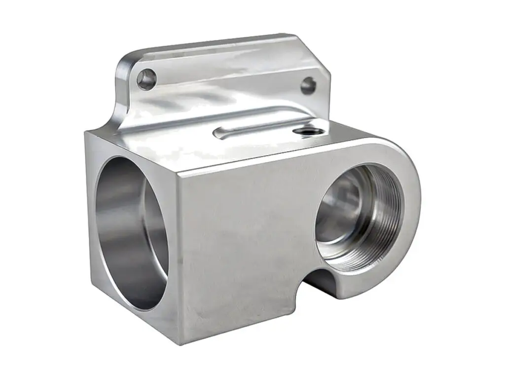
CNC machined 6061-T6 aluminium clevis blocks with two parallel bores held to H7, bore-to-bore parallelism 0.02 mm and a flat.

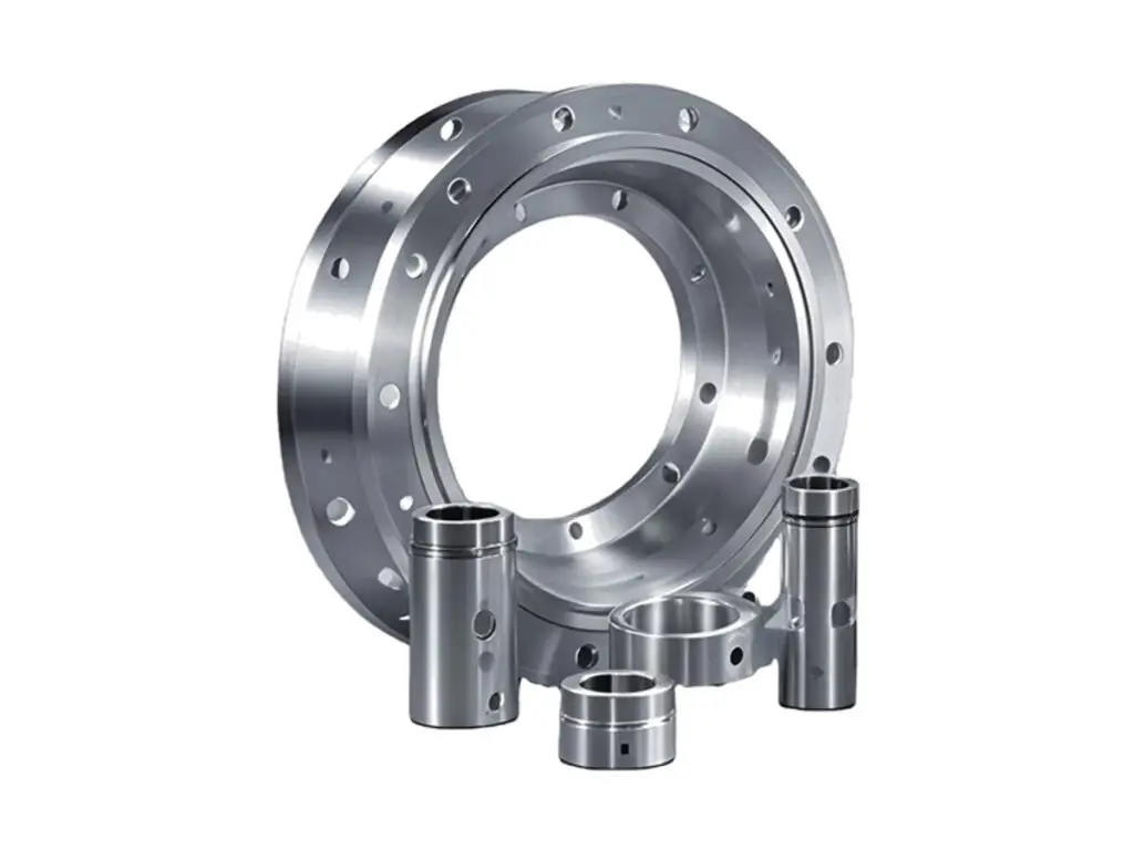
CNC turned 6061-T6 aluminium bearing ring flanges with a bored bearing seat to H7, bolt circle to ±0.03 mm, faces flat to 0.02 mm.

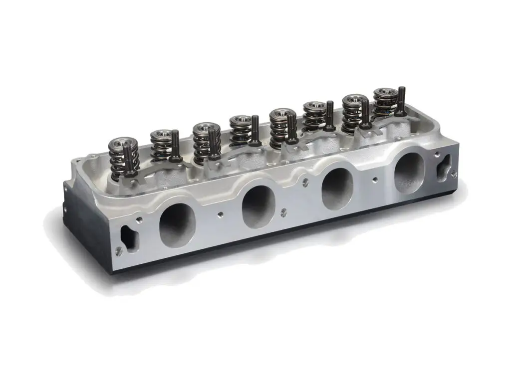
Five-axis machined billet aluminium cylinder heads with combustion chambers, valve seats and cam bores held to 0.015 mm, deck.

CNC turned aluminium stepped spacer bushings with parallel faces to 0.02 mm, stepped shoulder square to the bore and teal or.

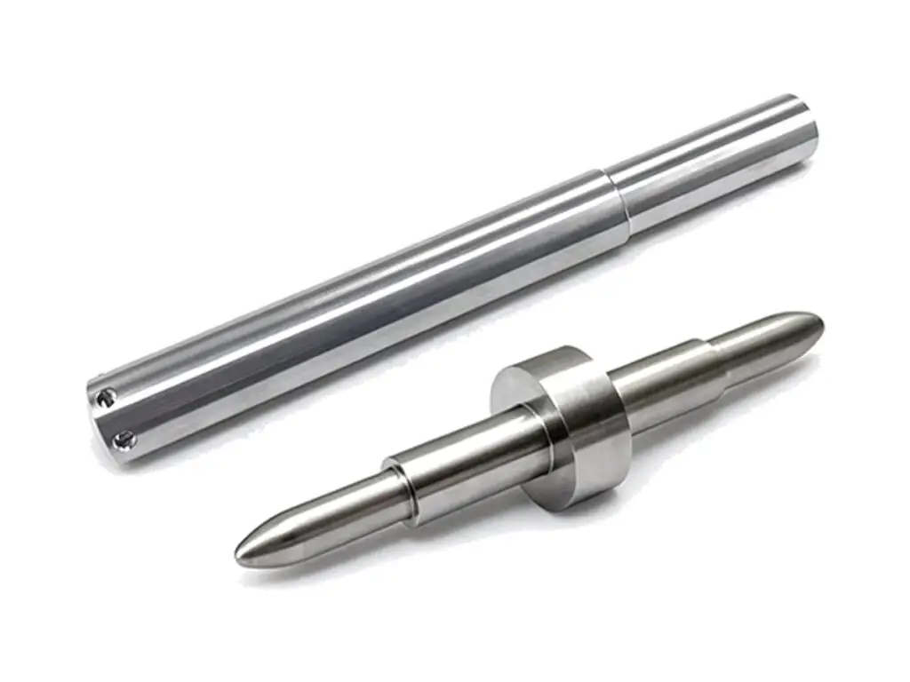
CNC turned aluminium guide shafts and positioning pins with stepped diameters ground to h6, straightness 0.02 mm per 100 mm and.

Get high‑quality machined parts in as fast as 4 days with our expanded automated CNC milling!

Scroll to Top