

Home / CNC-Machining / CNC 5-Axis Machining / Five-Axis CNC Machined Aluminum Cylinder Head
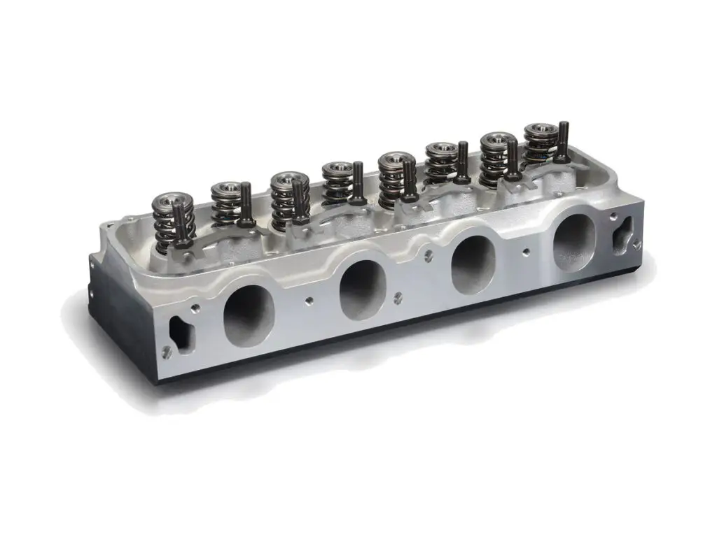
Five-axis machined billet aluminium cylinder head with a profiled combustion chamber and line bored cam tunnels

Five-Axis CNC Machined Aluminum Cylinder Head

Billet aluminium cylinder heads five-axis machined from 6061-T6 or 7075-T6, with combustion chambers profiled to a matched volume, valve seats coaxial to the guides within 0.015 mm, cam bores line bored to H6 and a deck flat to 0.02 mm. Ports are blended to the gasket line so the manifold does not step into the head.

*Send the cam, valve and gasket drawings together. A head is only as good as the stack around it, and the deck height is set by the cam base circle, not by the block.

Billet Cylinder Head Overview

A cylinder head is where flow, sealing and geometry meet: the deck has to seal combustion pressure, the chamber has to hold the volume the compression ratio was calculated from, and the cam bores have to stay in line while the head is hot.

The part is machined from a solid billet in three stages: roughing removes most of the mass, an intermediate pass brings the walls to 1 mm of finish, and the finishing passes cut the chambers, ports and seat pockets. Cam bores are line bored last, with the head clamped to a deck plate that reproduces the block.

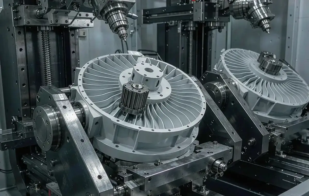
Five-axis machining of a vacuum pump impeller and a twin-body valve housing
6061-T6 aluminium flat plate stock for CNC milling

6061-T6 Billet

6061-T6 is the default for a naturally aspirated head: it welds if a port needs repair, holds a chamber edge without chipping and takes a thread insert cleanly. It is also stable enough that the deck stays flat after the chamber is cut.

7075-T6 aluminium billet block stock for CNC milling

7075-T6 for Boosted Engines

7075-T6 is chosen when the head sees boost and the deck load is high, because its yield strength keeps the fire ring from Brinelling the deck. It cannot be welded reliably, so a port repair means a new head.

Naturally aspirated and repairable points to 6061; high cylinder pressure and a known port shape points to 7075. The chamber volume target usually decides the rest.

Billet Cylinder Head Specifications

Five-axis data for billet heads, with the deck, chamber and cam bore values that decide whether the engine seals and makes the flow it was designed for.

SpecificationMachining DataSpecificationMachining Data
ProductBillet Cylinder Head / Head BlockMachining Process5-Axis CNC Milling, Chamber Profiling, Line Boring
Material6061-T6 or 7075-T6 BilletDeck Flatness0.02 mm over the full face
Combustion ChamberVolume Matched to ±1 cm³Valve Seat Coaxiality0.015 mm to the Guide
Cam BoreØ 22 – 40 mm, H6, Line BoredCam Bore Straightness0.01 mm over 400 mm
Valve Guide BoreØ 6 – 12 mm, H7Port MatchingWithin 0.5 mm of the Gasket
Deck Surface FinishRa 1.6 µm or BetterSpark Plug ThreadM10 – M14, Cut to Pre-Plate Size
CustomizationChamber Shape, Port Size, Injector Boss, Sensor PadsLead Time9 – 12 Days Sample, 18 – 24 Days Batch
InspectionCMM Chamber and Cam Bores, Volume Check, Flatness on GranitePackingTimber Crate, Deck Face Protected, VCI Bag

Key Features of Our Billet Heads

Chamber volume measured, cam bores line bored, deck checked on granite.

Chamber Volume Matched

Each chamber is measured by burette after machining and blended to within 1 cm³, so the compression ratio is the same across cylinders and the ECU trim stays balanced.

Cam Bores Line Bored in Place

Bores are cut with a line boring bar after the head is clamped to a deck plate, which keeps them straight to 0.01 mm over 400 mm and stops the cam binding when hot.

Seats Coaxial to Guides

The seat pocket is cut from the guide bore as the datum, holding coaxiality to 0.015 mm so the valve seals on the full face rather than on one side.

Ports Blended to the Gasket

Port openings are machined to the gasket line and blended 20 mm in, which removes the step that costs flow at the flange.

Head that has to hold volume and cam alignment?

Surface Finishes for Cylinder Heads

The deck and the chamber are functional surfaces; everything else is protection and appearance.

FinishMain PurposeFinishMain Purpose
Bead BlastingEven matte exterior that hides tool marksDeck Left BareTrue flat sealing surface under the gasket
Type II AnodizingColour and corrosion protection on the outsideCombustion Chamber PolishedReduces hot spots and carbon build-up
Laser MarkingCylinder number and torque sequence on the cam cover faceThread InsertsRepairs or upgrades for plug and sensor threads

*The deck is never anodized or blasted. Coating on a fire ring land adds a compressible layer that relaxes after a heat cycle and shows up as a gasket leak.

logo

Put your CNC milling parts into production today

All information and uploads are secure and confidential.

Trusted for Precision CNC Machined Components

Supporting OEM projects with accurate machining, flexible production, and reliable component quality.

Mechanical Equipment Customer
Chamber volumes matched within half a cc, so the ECU trims came out even across cylinders.

Industrial Components Buyer
The cam turns by hand in the tunnel, which is not something we could say about the last head.

Equipment Manufacturer
The deck was flat when we checked it on the block, so no surfacing before assembly.

OEM Customer
OEM Customer
Ports matched the gasket line, and the flow bench showed the numbers we had modelled.

Automation Industry Customer
The customized machining solution provided the dimensional accuracy required for our rotating equipment components.
Trusted for Precision CNC Milling.

Five-Axis Machining Process for Heads

The cam bores are line bored after the head is bolted to a deck plate, so the cam turns in a straight line rather than in the line the clamp load leaves.

01. Stack and Volume Review

Check the cam, valve, gasket and block drawings together, calculate the chamber volume target and confirm the deck height before any metal is removed.

02. Rough the Billet

Remove the bulk of the material in descending step-downs, leaving 1 mm on every finished face, then stress-relieve the part before the semi-finish pass.

03. Semi-Finish and Chamber

Bring walls to 0.3 mm, cut the chamber with a profile cycle and check the volume by burette, adjusting the cutter path before the finish pass.

04. Ports and Seat Pockets

Blend the ports to the gasket line, cut the seat pockets from the guide bore datum and ream the guides to H7, checking coaxiality on the CMM.

05. Line Bore Cams and Check Deck

Clamp the head to the deck plate, line bore the cam tunnels, then check deck flatness on granite and record every value before crating.

Send the head drawing with the cam and valve stack, and we will quote it with the chamber volume and cam alignment defined up front.

Billet Cylinder Head FAQs

Within 1 cm³ across cylinders, measured by burette after machining. For a race engine we match to 0.5 cm³, which needs a final blend by hand and a second measurement.

Yes, from a point cloud or a CAD surface. The port is machined to the model and blended to the gasket, but the flow bench result is only as good as the model you send.

We machine the pockets and bores to your insert drawings and can press and ream them if the inserts are supplied. Seat cutting after installation is done on a seat cutter, not on the mill.

0.02 mm over the full face, checked on a granite plate with a height gauge. Heads that are machined in two set-ups typically show 0.05 mm and need surfacing before assembly.

A billet head relaxes less than a casting, but the deck is worth re-checking after the first run-in. We leave 0.05 mm on the deck when the customer plans to surface after break-in.

Nine to twelve days including programming, roughing, stress relief, finishing, line boring and the CMM report. Batch runs of five or more take eighteen to twenty-four days.

Other CNC Machined Mechanical Components

Explore additional precision CNC machined components manufactured for OEM applications and customized production needs.

Custom CNC machined steel hydraulic manifold blocks with cross-drilled galleries and gauged ports.

Custom CNC machined stainless steel fixtures for automated assembly cells.

Precision CNC machined stainless steel rotary joint housings for robot arms and fluid transfer.

Custom CNC machined aluminum double tube clamps for motorcycle frames, bicycle builds and hydraulic lines.

Custom CNC machined hardened steel sleeves for robotic joints and motion assemblies.

Get high‑quality machined parts in as fast as 4 days with our expanded automated CNC milling!

Scroll to Top