

Home / CNC-Machining / CNC-Turning / CNC Turned Stainless Steel Valve Seat Spools
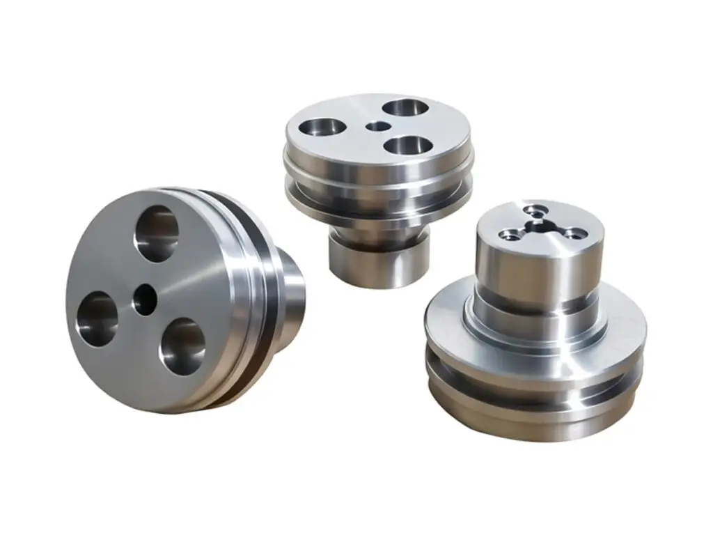
CNC turned stainless steel valve seat spools with ground sealing lands

CNC Turned Stainless Steel Valve Seat Spools

Valve seat spools turned from 316L stainless bar, with sealing lands ground to 0.005 mm and 0.003 mm roundness, shoulders square to 0.01 mm, land widths held to ±0.02 mm and seat faces lapped. Cross ports are drilled and deburred from both ends so no chip is left inside the spool.

*Send the sleeve bore with its actual measured size, not just the nominal. A spool ground to the nominal clearance will be tight in a sleeve that came in at the low limit.

Valve Seat Spool Overview

A spool is the moving part of a directional valve. Its lands seal against the sleeve bore, its shoulders set the stroke and its grooves route the flow. Clearance and roundness decide whether the valve creeps or sticks.

The spool is turned with grinding allowance on the lands, heat treated if required, then ground between centres so every land shares one axis. Seat faces are lapped last, and the cross ports are deburred before the final wash.

CNC turning of a brass threaded flange bushing, an aluminum bearing sleeve and a retaining cover disc
304L stainless steel round bar stock for CNC machining

316L Stainless Steel Bar

316L is used for water and mild chemical valves because it resists corrosion in the fine clearance between spool and sleeve, where stagnant fluid sits. It also work-hardens during grinding, which helps the land hold its size.

304L stainless steel plate and block stock for CNC machining

17-4PH or Hard Chrome on 316L

17-4PH is chosen when the valve works at high pressure and the land has to resist scoring. Hard chrome on 316L gives a low-friction surface at lower cost, but the plating thickness must be allowed for before grinding.

For a valve that cycles millions of times, the surface treatment matters more than the base alloy; for a valve in seawater, the alloy decides.

Valve Seat Spool Specifications

Turning and grinding data for spools, with the land, shoulder and port values that decide whether the valve seals.

SpecificationMachining DataSpecificationMachining Data
ProductValve Seat Spool / Spool SleeveMachining ProcessCNC Turning, Grinding, Lapping
Material316L Stainless Steel BarDiameter RangeØ 12 – 70 mm
Sealing DiameterGround to 0.005 mm, Roundness 0.003 mmSurface FinishRa 0.2 µm on Sealing Lands
Shoulder Squareness0.01 mm to the Spool AxisLand Width±0.02 mm
Groove Depth±0.02 mmConcentricity0.005 mm Between Lands
Through BoreØ 4 – 20 mm, H8Cross PortsØ 2 – 8 mm, Deburred Both Ends
CustomizationHard Chrome, Nitriding, Metering SlotsLead Time6 – 8 Days Sample, 12 – 16 Days Batch
InspectionMicrometer and Air Gauge, Roundness Tester, CMM ShoulderPackingIndividual Tube, Oil Coated, Carton

Key Features of Our Valve Spools

Turned with grinding allowance, ground on one axis.

Lands Ground Between Centres

Every land is ground from the same centres, so the spool has one axis and slides in the sleeve without a tight spot at mid-stroke.

Shoulders Square to 0.01 mm

The shoulders that set the stroke are machined square, so the valve opens at the same position from either direction.

Cross Ports Deburred Inside

Ports are deburred from both ends with a back-chamfer tool, so no burr is left to score the sleeve or break off into the circuit.

Seat Faces Lapped

The seat face is lapped flat after grinding, which is what stops internal leakage when the valve is closed.

Spool that has to seal without creeping?

Surface Finishes for Valve Spools

A coating on a ground land changes the clearance, so the finish is agreed before the final grind size.

FinishMain PurposeFinishMain Purpose
PassivationRemoves free iron after grindingHard Chrome PlatingWear resistance on the sealing lands
ElectropolishingLowers Ra on the spool bodyMasked LandsKeeps the ground diameter unchanged
LappingFinal seal on the seat faceOil CoatingCorrosion protection during shipping

*Hard chrome adds 10 to 25 µm per surface. Plated spools are ground undersize, plated, then ground to the finished land diameter and lapped.

logo

Put your CNC milling parts into production today

All information and uploads are secure and confidential.

Trusted for Precision CNC Machined Components

Supporting OEM projects with accurate machining, flexible production, and reliable component quality.

Mechanical Equipment Customer
The spools slide in the sleeves without a tight spot, and the valve does not creep.

Industrial Components Buyer
The lands are all the same size, so we no longer match spools to sleeves by hand.

Equipment Manufacturer
No burr inside the cross ports, and we have had no contamination failures since.

OEM Customer
OEM Customer
The seat faces sealed, and internal leakage is below our test limit.

Automation Industry Customer
The customized machining solution provided the dimensional accuracy required for our rotating equipment components.

Trusted for Precision CNC Milling.

Turning Process for Valve Spools

The sealing lands are ground after turning, so the spool slides in its sleeve without a visible step and the valve does not creep.

01. Sleeve and Clearance Review

Check the measured sleeve bore, the required clearance and the stroke against the drawing, and confirm the port positions before turning.

02. Turn With Grinding Allowance

Turn the spool, leaving 0.15 to 0.25 mm on the sealing lands, and cut the grooves and shoulders to width in the same set-up.

03. Drill Cross Ports

Drill the cross ports on the mill or a driven tool, then deburr both ends and wash the bore before heat treatment or plating.

04. Grind the Lands

Grind between centres to the finished land diameter, checking roundness and taper on an air gauge at both ends of each land.

05. Lap Seats and Protect

Lap the seat faces, passivate, oil coat and pack each spool in its own tube so the lands do not touch during transport.

Send the sleeve bore size and the stroke, and we will quote spools with the lands ground to 0.005 mm and the seats lapped.

Valve Seat Spool FAQs

Typically 3 to 8 µm on a 20 mm spool for hydraulic duty, and 10 to 15 µm for water. The right figure depends on the fluid viscosity and the temperature range, and we machine to the value you specify.

0.003 mm, measured on a roundness tester at three sections per land. That is what keeps the spool from sticking when the valve is cold.

Yes, 10 to 25 µm of hard chrome, applied before the final grind. The land is turned undersize and ground after plating to the finished diameter.

With a back-chamfer tool from the bore side after drilling, then a wash and a borescope check. A burr left inside will score the sleeve within a few hundred cycles.

We can, if you send the sleeves or their measured bores. Matched sets are numbered and packed together so the clearance is not lost at assembly.

0.002 mm by lapping, with Ra 0.2 µm. That is the surface that controls internal leakage when the valve is closed.

Other CNC Machined Mechanical Components

Explore additional precision CNC machined components manufactured for OEM applications and customized production needs.

Custom CNC machined aluminum intake manifolds for automotive and motorsport builds.

Custom CNC machined stainless steel multi jaw clamping plates for lathe, grinder and wheel hub fixtures.

Custom CNC machined aluminium indexing disks for rotary positioning systems.

Custom CNC machined aluminium housings for automation and electronic equipment.

Explore custom shock mount CNC milled parts in 6061 or 7075 aluminum, engineered for precise fit, stable suspension support, and.

Get high‑quality machined parts in as fast as 4 days with our expanded automated CNC milling!

Scroll to Top