

Home / CNC-Machining / CNC-Turning / CNC Turned Brass Carburetor Throttle Shaft
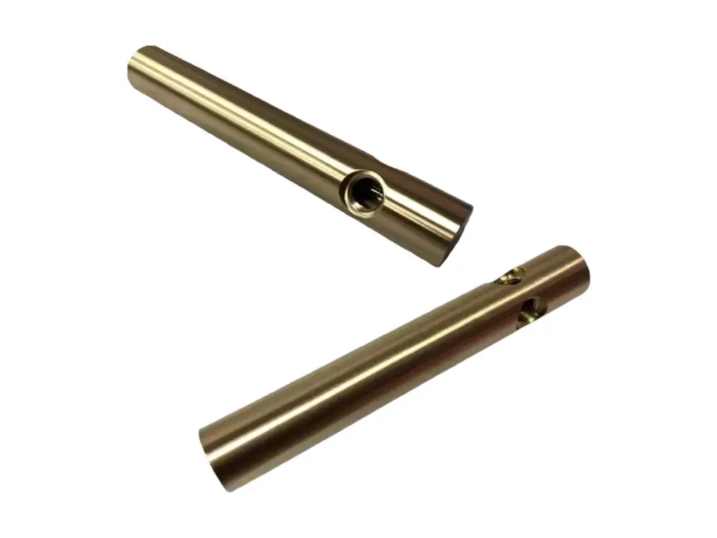
CNC turned brass carburettor throttle shaft with ground journals and a milled throttle flat

CNC Turned Brass Carburetor Throttle Shaft

Throttle shafts turned and ground from C36000 brass, with journals held to h6 and round to 0.005 mm at Ra 0.4 µm, straightness at 0.02 mm over the full length, the throttle flat milled square to 0.02 mm and shoulder spacing within 0.02 mm to control end float.

*Send the carburettor body bore and the throttle plate drawing. The flat depth sets the plate angle at idle, and 0.05 mm too deep turns a smooth idle into a 1,400 rpm hang.

Brass Throttle Shaft Overview

A throttle shaft is a small, precise spindle: two journals run in the body, a flat carries the throttle plate, and the ends take a lever and a return spring. If the flat is not square to the axis the plate binds in the bore and the throttle will not close fully.

The shaft is turned between centres with the journals left 0.05 mm oversize, then ground to h6, and the throttle flat is milled from the journals as the datum so the plate sits at the right angle.

CNC turning of a brass threaded flange bushing, an aluminum bearing sleeve and a retaining cover disc
304L stainless steel round bar stock for CNC machining

C36000 Brass

C36000 is used because it is stable in fuel, machines to a fine journal finish and does not seize in a brass or zinc carburettor body the way an aluminium shaft does when it corrodes.

304L stainless steel plate and block stock for CNC machining

303 Stainless or 2011 Aluminium

303 is chosen for ethanol-blended fuel and marine engines. 2011 aluminium is used in modern throttle bodies where weight matters and the body is also aluminium, hard anodized to reduce wear.

A brass shaft in an aluminium body needs a dry lubricant; without it the two metals corrode together and the throttle sticks after a season of storage.

Brass Throttle Shaft Specifications

Turning and grinding data for throttle spindles, with the journal, flat and end float values that decide whether the throttle closes cleanly.

SpecificationMachining DataSpecificationMachining Data
ProductThrottle Shaft / Carburettor SpindleMachining ProcessCNC Turning, Cylindrical Grinding, Milling
MaterialC36000 Brass, 303 Stainless on RequestEnvelopeØ 3 – 14 mm, Length 30 – 140 mm
Journalsh6, Roundness 0.005 mmJournal FinishRa 0.4 µm Ground
Throttle FlatMilled to 0.03 mm, Square to the Axis 0.02 mmFlat Length±0.10 mm
Straightness0.02 mm Over the Full LengthEnd Float0.02 mm Between Shoulders
Shaft EndsSlotted, Threaded or D-ShapedSlot Width±0.05 mm
Shoulder Spacing±0.02 mmRunout0.01 mm at the Journal
CustomizationLever Arm, Return Spring Hook, Cross Hole, Anti-Tamper SlotLead Time4 – 6 Days Sample, 10 – 14 Days Batch
InspectionMicrometer Journals, Runout Between Centres, Flat Depth GaugePackingTube per Shaft, Oiled Paper

Key Features of Our Throttle Shafts

Ground journals, flat cut from the journal datum, end float controlled.

Journals Ground, Not Just Turned

Grinding removes the 0.008 mm lobing a turning insert leaves, so the shaft runs in its bush without a high spot that shows as a sticky first few degrees of throttle.

Flat Cut From the Journal Datum

The throttle flat is milled with the journals as the datum, square to 0.02 mm, so the plate sits at the correct angle and seals against the bore at idle.

Shoulder Spacing Held to 0.02 mm

End float is set by the distance between the shoulders, not by a washer, so the shaft cannot walk and wear the body bore on one side.

Runout Checked Between Centres

Every shaft is indicated between centres after grinding, and anything above 0.01 mm at the journal is straightened or scrapped rather than shipped.

Shaft that has to let the throttle close?

Surface Finishes for Throttle Shafts

The journals are the bearing surface and must stay bare; the rest can be coated for appearance and wear.

FinishMain PurposeFinishMain Purpose
Natural BrassBearing surface as groundNickel PlatingWear resistance on the flat
Clear LacquerStops tarnish on shelfTin PlatingFuel resistance on brass
Bead BlastingMatte on the non-bearing lengthPassivationCleaning before coating
Plating Build3 – 5 µm, Journals MaskedUltrasonic CleanRemoves grinding swarf
Journal ProtectionCaps During CoatingAssembly OilLight Film, Fuel Compatible
Salt Spray72 h on plated shaftsStraightness CheckAfter Coating

*Plating on a journal closes an h6 fit by 6 to 10 µm and the shaft will not enter its bush. Journals are masked with a tape sleeve and checked again after coating.

logo

Put your CNC milling parts into production today

All information and uploads are secure and confidential.

Trusted for Precision CNC Machined Components

Supporting OEM projects with accurate machining, flexible production, and reliable component quality.

Mechanical Equipment Customer
The throttle closes to the stop now, and the idle is steady at last.

Industrial Components Buyer
The shaft went into the body bushes without reaming.

Equipment Manufacturer
The plate sits flat on the flat, so there is no bypass screw wound all the way in.

OEM Customer
OEM Customer
A season of running and the journals show no step.

Automation Industry Customer
The customized machining solution provided the dimensional accuracy required for our rotating equipment components.
Trusted for Precision CNC Milling.

Machining Process for Throttle Shafts

The journals are ground between centres after turning, so the shaft runs in its bushes without the 0.01 mm high spot that a turned finish leaves.

01. Body and Plate Review

Check the body bore, the plate thickness and the lever fixing, then set the journal size and the flat depth from the drawing.

02. Turn Between Centres

Turn the shaft between centres, leaving 0.05 mm on the journals and holding the shoulder spacing to ±0.02 mm.

03. Grind the Journals

Grind to h6 at Ra 0.4 µm, checking diameter and roundness on a micrometer stand before the shaft leaves the grinder.

04. Mill the Throttle Flat

Mill the flat from the journal datum, check depth and squareness, then cut the end slot or thread if the drawing calls for one.

05. Straighten, Check, Oil

Indicate runout between centres, straighten if needed, apply a fuel-compatible oil film and pack each shaft in its own tube.

Send the carburettor body and plate drawing, and we will quote a shaft with ground journals and the flat cut from the same datum.

Brass Throttle Shaft FAQs

A turned journal has 0.008 mm of lobing from the insert radius, which is enough to feel as a tight spot when the throttle opens from idle. Grinding removes it and holds roundness at 0.005 mm.

It follows the plate thickness and the bore angle, usually 0.5 to 0.8 mm. The depth is held within 0.03 mm because it sets the plate angle and therefore the idle bypass.

Yes, from the old shaft or a drawing. Worn journals are measured and the new shaft is made to nominal, not to the wear, since the body bore has usually worn too.

C36000 is stable in E10 and E85 but can dezincify in the presence of water and chlorides. For marine or long-storage engines we recommend 303 stainless instead.

Yes, a lever arm and spring hook can be cut from the same bar, which keeps the lever square to the flat and removes the need for a separate pinned joint.

0.02 mm between the shoulders as supplied. The body bore usually adds 0.02 to 0.05 mm, so the assembled float lands between 0.04 and 0.07 mm, which is the normal range for a butterfly throttle.

Other CNC Machined Mechanical Components

Explore additional precision CNC machined components manufactured for OEM applications and customized production needs.

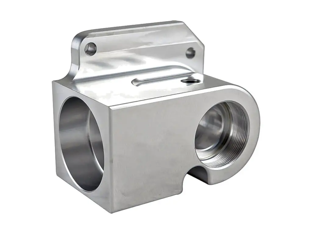
CNC machined 6061-T6 aluminium clevis blocks with two parallel bores held to H7, bore-to-bore parallelism 0.02 mm and a flat.

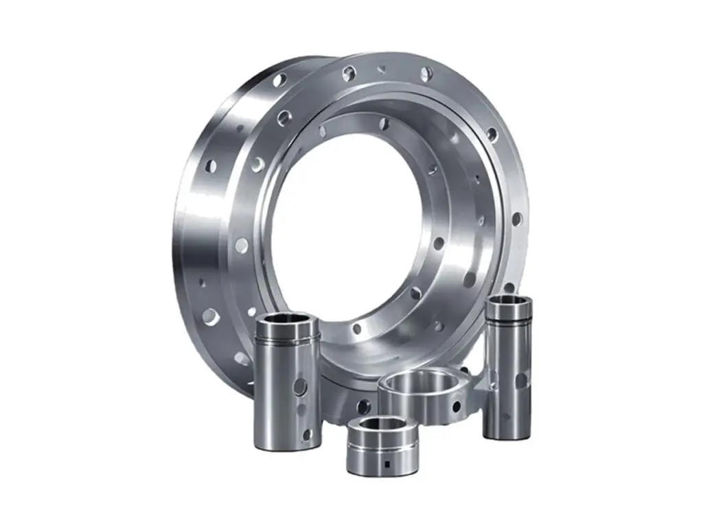
CNC turned 6061-T6 aluminium bearing ring flanges with a bored bearing seat to H7, bolt circle to ±0.03 mm, faces flat to 0.02 mm.

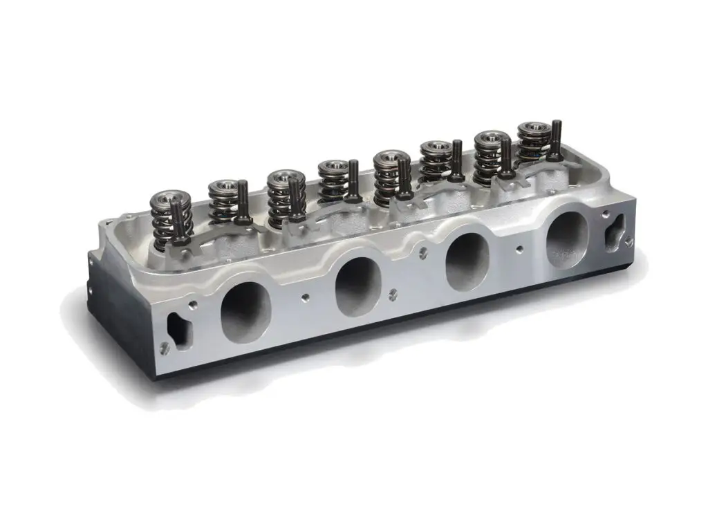
Five-axis machined billet aluminium cylinder heads with combustion chambers, valve seats and cam bores held to 0.015 mm, deck.

CNC turned aluminium stepped spacer bushings with parallel faces to 0.02 mm, stepped shoulder square to the bore and teal or.

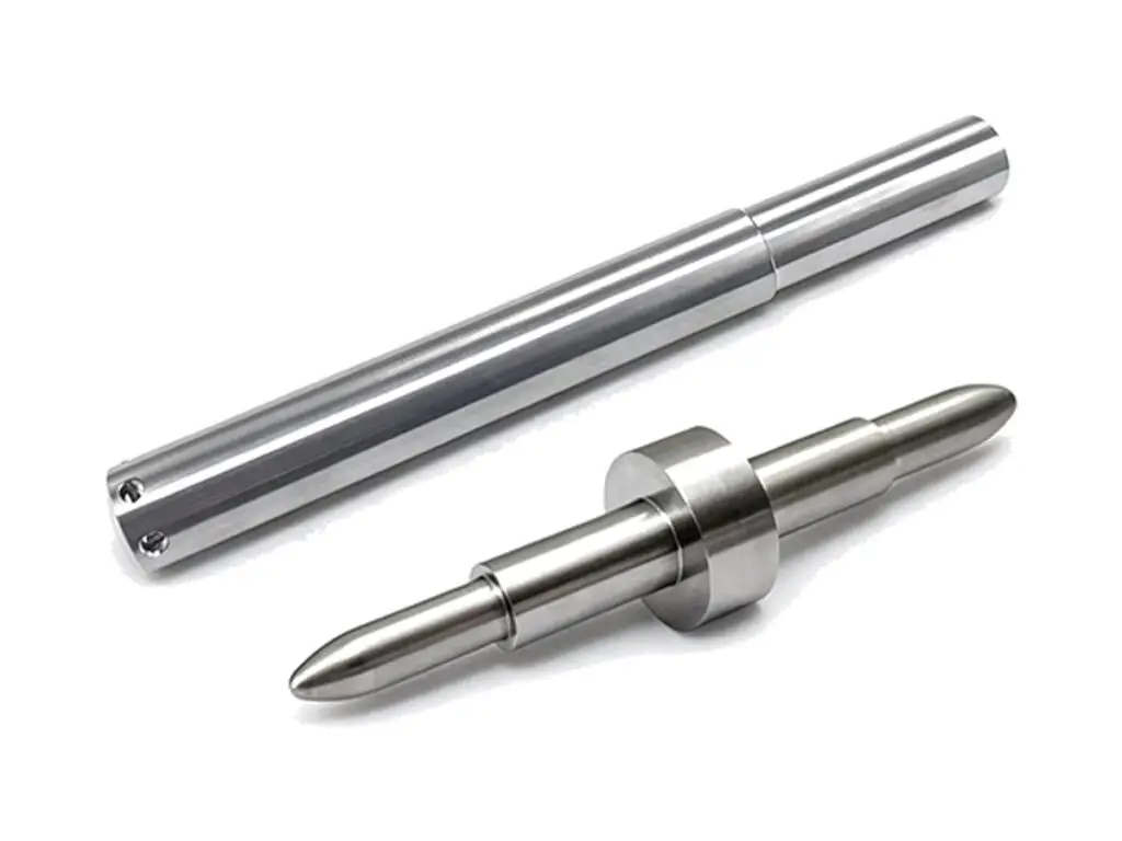
CNC turned aluminium guide shafts and positioning pins with stepped diameters ground to h6, straightness 0.02 mm per 100 mm and.

Get high‑quality machined parts in as fast as 4 days with our expanded automated CNC milling!

Scroll to Top