

Home / CNC-Machining / CNC-Turning / CNC Turned Aluminum Eight-Lobe Flange Plate
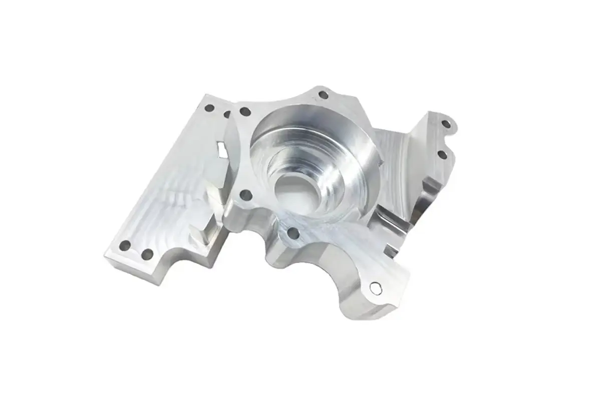
CNC turned aluminum eight-lobe flange plate with a bored pilot and a drilled bolt circle

CNC Turned Aluminum Eight-Lobe Flange Plate

Eight-lobe flange plates turned and milled from 6061-T6, with a H7 pilot bore round to 0.015 mm, eight lobes indexed to ±0.05 mm, a bolt circle within 0.05 mm of the bore axis and faces flat to 0.02 mm.

*Send the mating spigot and the bolt pattern. The lobe index is set from the pilot bore, and a plate indexed from the outside edge will be 0.1 mm out at the last lobe.

Eight-Lobe Flange Plate Overview

A scalloped flange is a clocking part: the lobes have to be equally spaced, the bolt circle has to be concentric to the pilot bore and the face has to be flat, or the joint opens at one lobe when the bolts are torqued.

The plate is turned to thickness and bored first, then moved to the mill where the eight lobes are cut with the bore as the rotary datum before the bolt circle is drilled from the same centre.

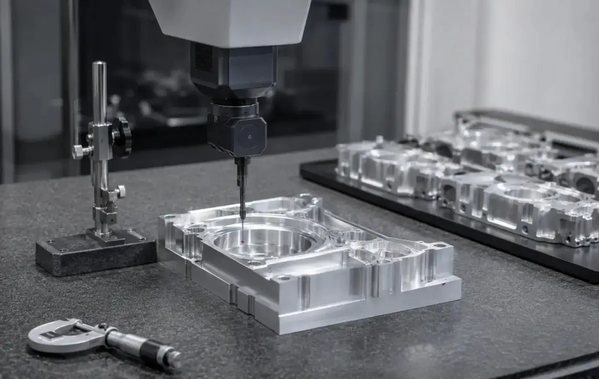
CMM inspection of a gripper jaw set, a brass manifold block and an eight-lobe flange plate
6061-T6 aluminium flat plate stock for CNC milling

6061-T6 Aluminium Plate

6061-T6 is used for flange plates because the lobes remove a lot of section and the remaining rim still has to carry bolt preload. It also anodizes evenly on the scalloped edges.

7075-T6 aluminium billet block stock for CNC milling

6082-T6 or 5083

6082 is used where the plate is welded to a duct or a housing, and 5083 where the flange sees salt water and the anodized surface has to resist pitting at the lobe edges.

Above 250 mm diameter the plate is turned from cast or rolled plate and stress relieved before the lobes are cut, otherwise the rim goes out of flat by 0.05 mm after machining.

Eight-Lobe Flange Plate Specifications

Turning and milling data for scalloped flanges, with the bore, lobe index and bolt circle values that keep the plate interchangeable.

SpecificationMachining DataSpecificationMachining Data
ProductEight-Lobe Flange Plate / Scalloped FlangeMachining ProcessCNC Turning, Milling, Bolt Circle Drilling
Material6061-T6 Aluminium PlateEnvelopeØ 90 – 320 mm
Pilot BoreØ 20 – 160 mm, H7Bore Roundness0.015 mm
Flange Thickness8 – 25 mmFace Flatness0.02 mm
Lobe Count6 – 12 Lobes, Equal IndexLobe Index±0.05 mm
Bolt Circle4 – 12 Holes, Position ±0.05 mmCounterboreDepth ±0.05 mm
ConcentricityBolt Circle to Bore 0.03 mmSurface FinishRa 1.6 µm Faces, Ra 0.8 µm Bore
CustomizationSpigot, Keyway, Lightening Pockets, O-Ring GrooveLead Time5 – 7 Days Sample, 12 – 16 Days Batch
InspectionAir Gauge Bore, CMM Bolt Circle and Lobe Index, Granite FlatnessPackingFoam Cradle, Bore Plug, Boxed

Key Features of Our Flange Plates

Lobes and bolt circle from the bore, faces flat before coating.

Lobes Indexed From the Pilot Bore

Each lobe is cut with the bore as the rotary datum, so the index stays within 0.05 mm and any of the eight positions lines up with the mating duct.

Bolt Circle From the Same Centre

The bolt holes are drilled from the bore axis rather than the outside diameter, so the plate does not fight the bolts when it is fitted.

Faces Flat to 0.02 mm

Both faces are skimmed after the lobes are cut, because scalloping the rim releases stress and dishes the plate by 0.03 mm if the faces are finished first.

Bore Masked Before Coating

The pilot bore is plugged for anodizing and air gauged again afterwards, so the spigot still goes in with the fit it was machined to.

Flange that has to clock into eight positions?

Surface Finishes for Flange Plates

The pilot bore and the mounting face are fits, the scalloped edge is visible and the bolt holes must stay clear.

FinishMain PurposeFinishMain Purpose
Type II AnodizingCorrosion protection and colourHard AnodizingWear resistance on the spigot
Masked Pilot BoreBore stays at H7 after coatingBead BlastingEven matte before dye
Laser MarkingBolt pattern and balance positionMasked Flange FaceKeeps the mounting face flat and conductive
Anodizing Build10 – 15 µm, SealedVapour BlastingSatin Finish Between Lobes
Bore PlugRemoved After CoatingFace ProtectionTaped for Shipping
Assembly OilLight Film in the BoreBalance CheckStatic Balance Within 10 g·mm

*Anodizing closes the pilot bore by 20 µm and builds unevenly on a scalloped edge. The bore is plugged and the mounting face is taped, otherwise the plate sits 0.01 mm proud and the joint leaks.

logo

Put your CNC milling parts into production today

All information and uploads are secure and confidential.

Trusted for Precision CNC Machined Components

Supporting OEM projects with accurate machining, flexible production, and reliable component quality.

Mechanical Equipment Customer
The plate clocked into any of the eight positions, exactly as it should.

Industrial Components Buyer
The face was flat, and the joint did not leak at any lobe.

Equipment Manufacturer
The bolt holes lined up with the duct without opening one out.

OEM Customer
OEM Customer
The bore was a proper fit, so the spigot centred without a mallet.

Automation Industry Customer
The customized machining solution provided the dimensional accuracy required for our rotating equipment components.

Trusted for Precision CNC Milling.

Machining Process for Flange Plates

The lobes and the bolt circle are cut from the pilot bore, so the flange indexes the same way whichever of the eight positions it is turned to.

01. Spigot and Pattern Review

Check the mating spigot, the bolt pattern and the number of lobes, then set the index and the bolt circle from the bore.

02. Turn Faces and Bore

Turn both faces, the outside diameter and the pilot bore in one set-up, leaving 0.5 mm on the faces for a final skim.

03. Cut the Lobes

Mount on the bore, index each lobe from the same datum and mill the scallops, checking the index with a pin before unclamping.

04. Drill the Bolt Circle

Drill and counterbore the bolt circle from the bore axis, then skim both faces to remove the burr left by the lobes.

05. Inspect, Mask, Anodize

CMM the bolt circle and lobe index, air gauge the bore, plug the bore, anodize, then re-gauge and protect the faces.

Send the spigot drawing and the bolt pattern, and we will quote a flange plate with the lobes and the bolt circle cut from the pilot bore.

Eight-Lobe Flange Plate FAQs

0.05 mm between lobe centres, cut with the bore as the rotary datum. An error of 0.1 mm means the plate only fits in one of the eight positions, which defeats the point of a scalloped flange.

Yes, a spigot from 5 to 25 mm deep is turned in the same set-up as the bore, so the spigot and the bore are concentric within 0.02 mm and the plate self-centres.

Because cutting the lobes releases stress in the rim and dishes the plate by about 0.03 mm. Skimming after the lobes is what keeps the face flat to 0.02 mm.

It adds 10 to 15 µm per surface, so the bore is plugged and re-gauged after coating. The mounting face is taped so the joint stays flat and conductive.

Yes, statically to 10 g·mm by milling a pocket on the heavy side, which matters on a fan or a rotating flange above 1,000 rpm.

320 mm from one plate. Above that the flange is turned as a ring and welded to a hub, which keeps the face flat but adds a weld that has to be stress relieved.

Other CNC Machined Mechanical Components

Explore additional precision CNC machined components manufactured for OEM applications and customized production needs.

Custom CNC machined steel hydraulic connectors and adapters for 350 bar systems.

Custom CNC machined aluminium brackets for textile machinery and automation frames.

Custom CNC machined aluminium cavity bases for automation and electronic equipment.

Explore CNC milled clutch levers in 6061 or 7075 aluminum, built for smooth pivot movement, accurate fit, comfortable control,.

Custom CNC machining milling aluminum engine brackets with 6061/7075 aluminum, complex milling, multiple finishes and precision.

Get high‑quality machined parts in as fast as 4 days with our expanded automated CNC milling!

Scroll to Top