

CNC Machined Robot Fixture Base Plate
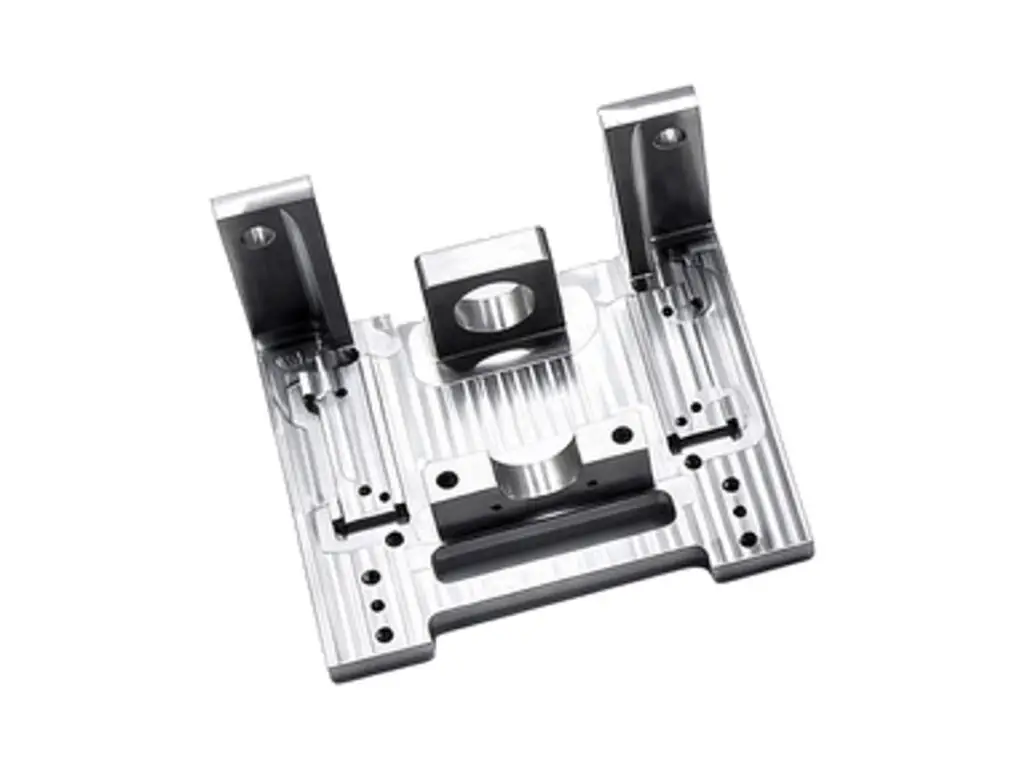
Robot fixture base plates machined from 6061-T6: 200 × 160 × 15 mm, two Ø10 H7 datum bores at a 150 mm spacing held to ±0.01 mm, three 12 mm T-slots at ±0.05 mm, sixteen M8 clamp holes and a top face flat to 0.02 mm. The plate is rough-machined, stress-relieved and then finished so the datum does not drift after unclamping.
- Datum Bores ±0.01 mm
- Top Face 0.02 mm
- T-Slots ±0.05 mm
- Flatness 0.03 mm
*Tell us the robot mounting pattern and the clamp type. The datum spacing is what every fixture on the plate is built from, and 0.02 mm of drift there repeats on every part the cell makes.
Robot Fixture Base Plate Overview
A fixture base plate is the reference every other fixture in the cell is built on. It has to be flat, the datum bores have to be exactly the spacing the robot program expects, and the T-slots have to run parallel so a clamp can be moved without re-teaching the cell.
The plate is faced, rough-slotted and then stress-relieved to remove the internal stress that a 15 mm plate carries after rolling. The datum bores are bored in a final clamping after relief, the T-slots are cut with a T-slot cutter in two passes and the top face is fly-cut to 0.02 mm.
6061-T6 Aluminium
6061-T6 gives a 1.35 kg plate that a robot can carry as an end-effector base and still hold a datum bore without the plate ringing under clamp load.
7075-T6 or Cast Tooling Plate
7075-T6 is used when the plate is heavily pocketed, and cast tooling plate is chosen for large plates where the residual stress of rolled plate would move the datum after machining.
A plate thinner than 12 mm will deflect between the T-slots under clamp load; 15 mm is the practical minimum for a 200 mm span.
Fixture Base Plate Specifications
Datum, slot and flatness values, all measured after stress relief.
| Specification | Machining Data | Specification | Machining Data |
|---|---|---|---|
| Product | Robot Fixture Base Plate | Process | CNC Milling, Boring, Slotting |
| Material | 6061-T6 Aluminium | Envelope | 200 × 160 × 15 mm |
| Datum Bores | 2 × Ø10 H7, ±0.01 mm | Datum Spacing | 150 mm ±0.01 mm |
| T-Slots | 3 × 12 mm Wide, ±0.05 mm | Slot Depth | 8 mm |
| Top Face | Flatness 0.02 mm, Ra 1.6 | Bottom Face | Parallel 0.03 mm |
| Clamp Holes | 16 × M8 × 1.25, 6H | Edge Break | 0.5 mm All Round |
| Load Capacity | Static 40 kN | Weight | Approx. 1.35 kg |
| Inspection | CMM Datum Check, Granite Flatness | Batch Size | 10 to 500 Pieces |
| Finish | Clear or Black Anodizing | Drawing Format | STEP, DXF, PDF |
A Datum That Does Not Move
Stress relief between roughing and finishing, then bored and fly-cut.
Stress-Relieved Before Finishing
The plate is roughed, relieved in a low-temperature cycle and only then finished, so the datum bores do not close up by 0.02 mm the day after machining.
Datum Bores Bored, Not Drilled
Both Ø10 H7 bores are bored in one clamping with the plate on a granite-style fixture, holding the 150 mm spacing to ±0.01 mm and roundness to 0.008 mm.
T-Slots Cut in Two Passes
Each slot is roughed with an end mill and finished with a T-slot cutter at a controlled feed, which keeps the slot floor parallel and the 12 mm width within 0.05 mm.
Every Plate Measured and Recorded
The datum spacing, flatness and slot positions are recorded against the plate serial and shipped with the inspection report, so the cell can be re-set from the sheet.
Fixture plate that has to repeat?
Surface Finishes for Fixture Plates
The datum and slot floors stay bare; the rest can be coated.
| Finish | Main Purpose | Finish | Main Purpose |
|---|---|---|---|
| Clear Anodizing | General protection, datum bores masked | Black Anodizing | Vision-system background |
| Hard Anodizing | Wear face under sliding clamps | Bead Blasting | Matte, non-reflective top face |
| Masked Datum | Bare bores for locating pins | Laser Marking | Grid and datum labels |
| Chromate Conversion | Conductive plate for grounding | Edge Sealing | Anodizing kept off the T-slot floor |
| Ultrasonic Clean | Chip removal from slots | Protective Film | Scratch-free shipping |
| Deburr Only | Plates that will be re-machined | Inspection Report | Datum values recorded per plate |
*Anodizing on a T-slot floor changes the clamp height by 20 µm; slot floors and datum bores are masked so clamps sit at the drawn height.
Put your CNC milling parts into production today
All information and uploads are secure and confidential.
Trusted for Precision CNC Machined Components
Supporting OEM projects with accurate machining, flexible production, and reliable component quality.
Trusted for Precision CNC Milling.
How We Machine a Fixture Base Plate
The two datum bores are bored after the plate is stress-relieved, so the 150 mm spacing does not move when the plate is unclamped.
01. Robot and Clamp Review
Check the robot mounting pattern, the clamp type and the load, then set the datum spacing and slot layout from the cell drawing.
02. Rough Face and Slot
Face both sides, rough the T-slots 0.5 mm oversize and drill the clamp holes, leaving 0.4 mm on the top face for the finish cut.
03. Stress Relief
Relieve the plate in a controlled cycle, then re-face the bottom so the plate sits flat on the machine table for the finishing operations.
04. Bore Datum and Finish Slots
Bore the two Ø10 H7 datums in one clamping, finish the T-slots with a T-slot cutter and fly-cut the top face to 0.02 mm.
05. Anodize With Masking and Certify
Mask the datum bores and slot floors, anodize, then measure the plate on the CMM and issue the datum report.
Send the robot mounting pattern and the clamp drawing, and we will quote a plate with the datum bored to ±0.01 mm and a flatness report with every plate.
Fixture Base Plate FAQs
0.02 mm on the top face and 0.03 mm parallel to the bottom, measured on a granite plate after the plate has stabilised at room temperature.
A rolled 15 mm plate carries internal stress that is released as material is removed, and the datum can move 0.03 mm overnight without relief.
Yes, from the robot drawing or a sample plate. The datum spacing and the bolt pattern are the two features we copy exactly.
We can fit ground pins to the datum bores and ream them in place, so the pin spacing is measured after fitting rather than assumed.
A 15 mm 6061 plate at this size is rated to 40 kN static in the clamp direction. Above that we quote a 20 mm plate or a steel base.
Yes. The top face has 1 mm of stock above the minimum thickness, so it can be skimmed once and the datum re-certified.
Other CNC Machined Mechanical Components
Explore additional precision CNC machined components manufactured for OEM applications and customized production needs.
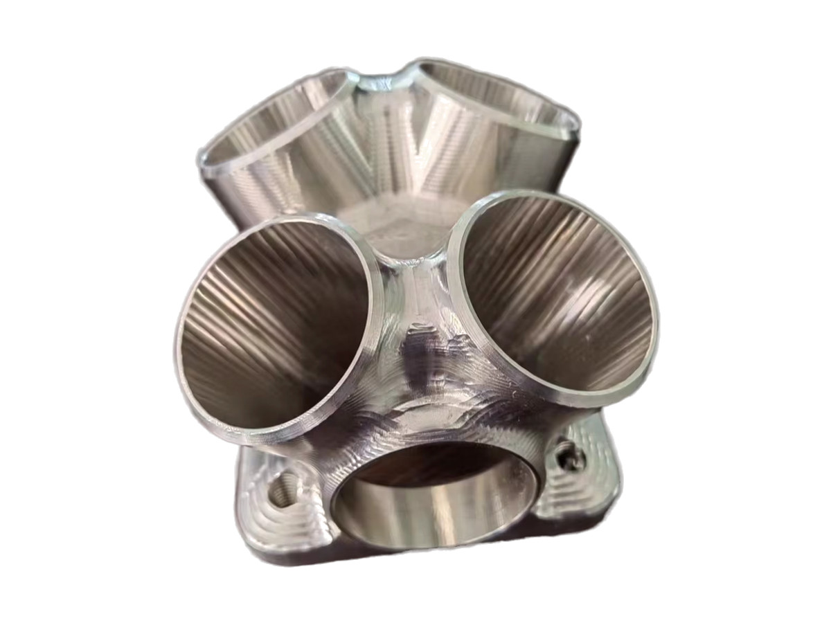
Five-axis CNC machined stainless steel spider hubs with four curved lobes, compound-angle bores and a central spline, held to.
CNC machined 6061-T6 aluminium gearbox end housings with a bearing bore to H7, a lapped seal face and a dowelled joint face,.
CNC turned 6061-T6 aluminium hose fittings with a barbed or threaded spigot, a sealing face and an anodized body, holding thread.
CNC turned stainless steel mounting discs with a recessed centre, four-hole bolt pattern, flat faces to 0.02 mm and a machined OD.
Five-axis machined 6082 aluminium hydraulic valve manifolds with ports on four faces, cross-drilled galleries, flat port faces.
Get high‑quality machined parts in as fast as 4 days with our expanded automated CNC milling!