
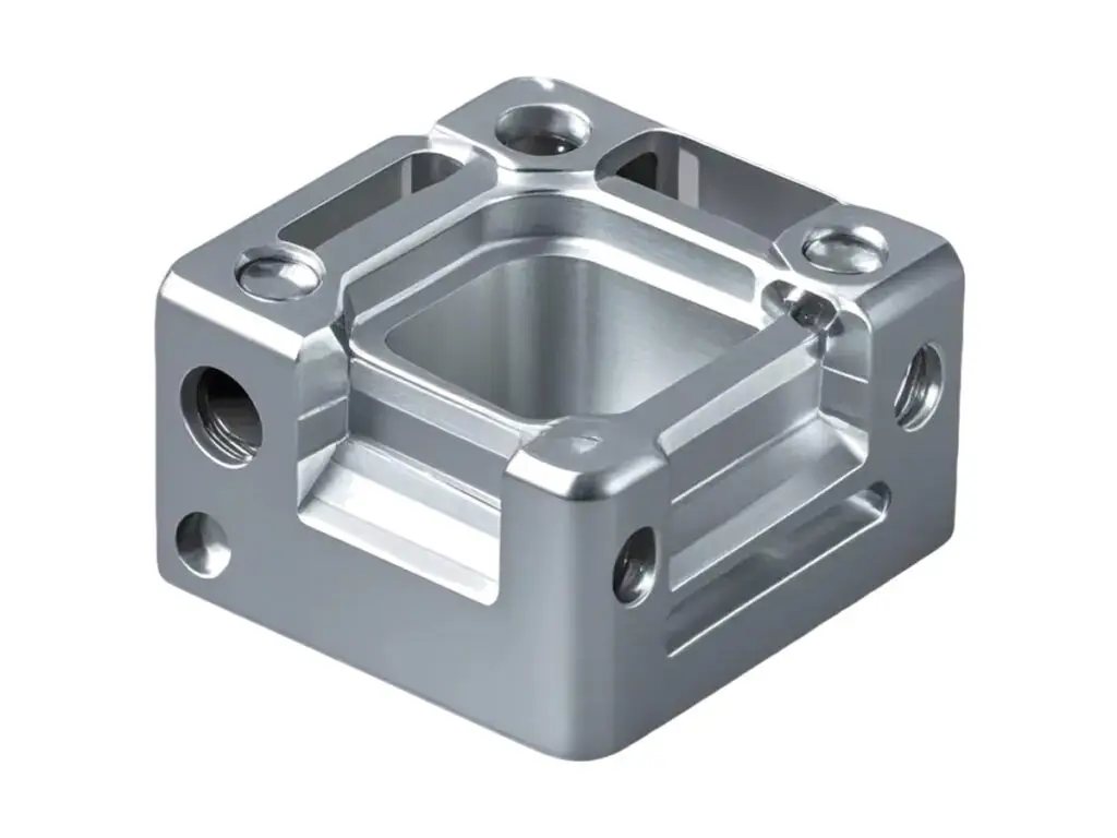


CNC Machined Aluminum Gearbox End Housing
Gearbox end housings machined from 6061-T6 plate or casting, with a bearing bore held to H7 and 0.01 mm roundness, a seal face lapped flat to 0.01 mm, a joint face flat to 0.02 mm and dowel holes positioned to ±0.02 mm. The bore is coaxial to the joint register within 0.015 mm.
- Bearing Bore to H7
- Seal Face Flat 0.01 mm
- Joint Face Coaxial 0.015 mm
- Dowel Holes in Line
*Send the shaft drawing and the seal section. The bore size, the seal counterbore depth and the joint face flatness are all set by the seal, not by the housing outline.
Gearbox End Housing Overview
An end housing closes the gearbox, carries one end of a shaft and holds the oil seal. If the bore is not coaxial with the joint, the shaft runs at an angle, the gear mesh goes tight at one point per revolution and the seal weeps.
The joint face is machined first and used as the datum for the bore, so the two cannot drift apart. The bore is bored and then air-gauged, the seal counterbore is cut with a form tool, and the face is lapped before the part is cleaned and plugged.
6061-T6 Aluminium Plate
Plate is used for prototypes and low volume because it is stress-relieved and stays flat after the joint face is cut. It also takes a lapped seal face without the porosity that can open up in a casting.
A356-T6 Casting or 7075-T6
A356 casting is used above roughly 500 units, where the shape is close to net and only the bore and faces are machined. 7075-T6 is chosen when the housing also carries a bearing preload and the wall cannot grow.
Castings need pressure testing for porosity before machining; plate does not. That single difference often decides the process at 200 to 500 units.
Gearbox End Housing Specifications
Boring and milling data for gearbox end covers, with the bore, seal face and joint values that keep the shaft true.
| Specification | Machining Data | Specification | Machining Data |
|---|---|---|---|
| Product | Gearbox End Housing / End Cover | Machining Process | 3-Axis CNC Milling, Boring, Lapping |
| Material | 6061-T6 Aluminium Plate or Casting | Envelope | Up to 260 × 220 × 90 mm |
| Bearing Bore | Ø 30 – 120 mm, H7, Roundness 0.01 mm | Bore Coaxiality | 0.015 mm to the Joint Face Register |
| Seal Face | Flatness 0.01 mm, Ra 0.8 µm | Joint Face Flatness | 0.02 mm |
| Dowel Holes | Ø 6 – 12 mm, H7, Position ±0.02 mm | Wall Thickness | 5 – 12 mm |
| Bolt Pattern | M6 – M12, Position ±0.05 mm | Oil Gallery | Ø 4 – 8 mm, Position ±0.10 mm |
| Customization | Breather Boss, Oil Level Plug, Sensor Pad | Lead Time | 6 – 8 Days Sample, 12 – 16 Days Batch |
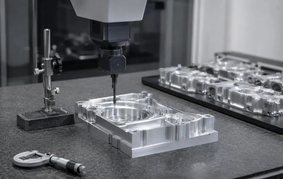
| Inspection | CMM Bore and Dowel Position, Air Gauge Bore, Seal Face Flatness | Packing | Bore Plugged, Foam Cradle, Carton |
Key Features of Our End Housings
Joint face first, then the bore from that datum.
Bore Machined From the Joint Face
The bearing bore is cut with the joint face as datum, holding coaxiality to 0.015 mm so the shaft does not run at an angle in the gearbox.
Seal Face Lapped, Not Just Faced
Lapping removes the facing feed mark and holds flatness to 0.01 mm, which is what stops a lip seal from weeping at the bottom of the cover.
Dowel Holes in Line With the Housing
Dowel holes are positioned to ±0.02 mm and reamed to H7, so the cover goes back on the same way after a rebuild.
Oil Gallery Drilled After Boring
The gallery is drilled after the bore is finished, so the breakout into the bore is clean and does not leave a burr inside the bearing seat.
Cover that has to keep a shaft coaxial?
Surface Finishes for End Housings
The bore and joint face are fits; the outside is a corrosion surface; the seal land is a wear surface.
| Finish | Main Purpose | Finish | Main Purpose |
|---|---|---|---|
| Type II Anodizing | Corrosion protection on the external faces | Hard Anodizing | Wear resistance on the seal land |
| Masked Bore and Joint Face | Keeps the bearing fit and the joint flat | Bead Blasting | Matte finish before dye |
| Laser Marking | Rotation arrow and breather position | Chromate Conversion | Conductive housing for an earth strap |
*Anodizing grows 5 to 10 µm and would close a H7 bore. Bores and joint faces are masked, and hard-anodized seal lands are machined undersize and lapped after coating.
Put your CNC milling parts into production today
All information and uploads are secure and confidential.
Trusted for Precision CNC Machined Components
Supporting OEM projects with accurate machining, flexible production, and reliable component quality.
Trusted for Precision CNC Milling.
Machining Process for End Housings
The bearing bore and the joint face are machined in the same set-up, so the shaft sits square to the gearbox instead of being pulled over by the cover.
01. Shaft and Seal Review
Check the shaft diameter, the bearing width and the seal section against the housing, and confirm the oil gallery route before the first cut.
02. Machine the Joint Face
Face the joint side and establish it as datum A, then machine the outside profile so the part can be held for boring without distorting the joint.
03. Bore and Lap the Seal Face
Bore the bearing seat to H7, cut the seal counterbore, then lap the seal face flat to 0.01 mm and check with a straight edge and light.
04. Dowels, Bolts and Gallery
Drill and ream the dowel holes, drill the bolt pattern, then drill the oil gallery and deburr the breakout inside the bore.
05. Clean, Mask and Measure
Clean the bore, plug it, mask the fits, anodize, then CMM the bore and dowel positions and air gauge the bore before packing.
Send the shaft and seal drawing, and we will quote an end housing with the bore coaxial to the joint within 0.015 mm.
Gearbox End Housing FAQs
Because the shaft position is set by the joint. Boring first and facing later means every tolerance between the two operations adds to the shaft misalignment, and the gear mesh goes tight.
0.01 mm after lapping, with Ra 0.8 µm. A faced-only surface holds 0.03 mm and leaves a feed mark that a lip seal will follow and weep along.
Yes, from the mating drawing or a measured sample. The pattern is drilled to ±0.05 mm and the dowel holes to ±0.02 mm, so the cover fits without opening the holes.
Castings are dye-penetrant inspected on the bore and joint face before machining, and pressure tested after if the drawing calls for an oil-tight housing.
H7 is standard, with roundness of 0.01 mm and 0.015 mm coaxiality to the joint register. A press-fit bearing can be supplied to P6 on request.
Yes. The gallery is drilled after boring and the breakout is deburred with a back-chamfer tool, because a burr there scores the bearing as it is pressed in.
Other CNC Machined Mechanical Components
Explore additional precision CNC machined components manufactured for OEM applications and customized production needs.
Precision CNC machined aluminum multi hole fixture plates with a lapped grid of locating holes.
Custom CNC machined aluminum motor housings with bored bearing seats, cooling fins and mounting flanges.
Custom CNC machined aluminum hollow sleeve connectors for robot arm segments and linear modules.
Custom CNC machined aluminium brake booster check valve bodies for motorcycles and automotive systems.
Custom CNC machined aluminium mounting brackets for robots, automation and equipment mounting.
Get high‑quality machined parts in as fast as 4 days with our expanded automated CNC milling!



