


Home / CNC-Machining / CNC 5-Axis Machining / Five-Axis CNC Machined Aluminum Hydraulic Valve Manifold
Five-axis machined 6082 aluminium hydraulic valve manifold with ports on four faces and cross-drilled galleries

Five-Axis CNC Machined Aluminum Hydraulic Valve Manifold

Hydraulic valve manifolds five-axis machined from 6082-T6 block, with four to fourteen ports spread over four faces, cross-drilled galleries, cartridge cavities and port faces flat to 0.02 mm. Every block is ultrasonically cleaned, borescoped and pressure tested at 1.5 times its rating before the ports are plugged and the map is issued.

*Send the hydraulic schematic and the machine envelope. A manifold is a routing decision as much as a machining one, and the drawing that matters is where the hoses have to land.

Hydraulic Valve Manifold Overview

A manifold replaces a wall of fittings with holes in a block. That only pays off if the holes meet where the schematic says and the block is small enough to fit where the hoses need it, which is why the port layout is designed before the block is drawn.

The block is squared, datum faces are marked, and ports are machined from those datums on a five-axis machine so the faces that sit at an angle are cut without a separate fixture. Galleries are drilled in stages, cleaned, borescoped and then proven by the pressure test.

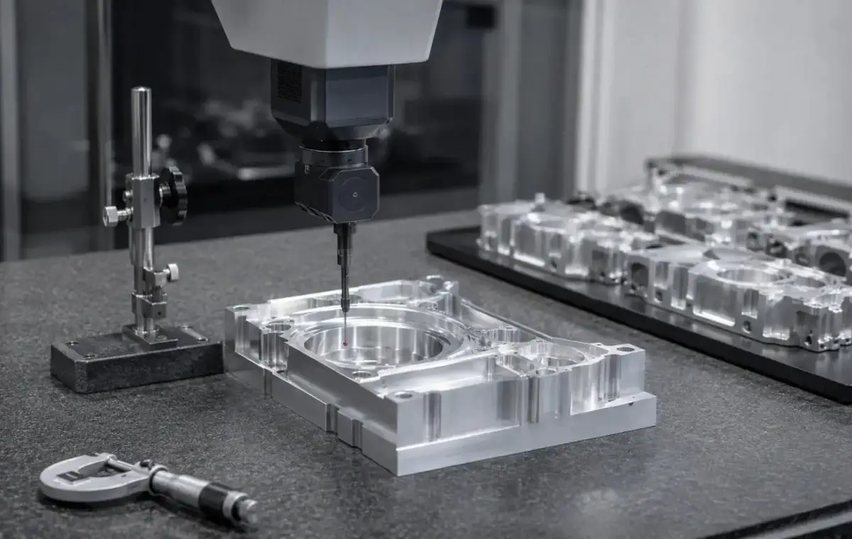
CMM inspection of a gripper jaw set, a brass manifold block and an eight-lobe flange plate
6061-T6 aluminium flat plate stock for CNC milling

6082-T6 Aluminium Block

6082-T6 is the usual choice for a mobile or machine-tool manifold because it is strong enough for 250 bar at a 2.5 mm wall and anodizes hard enough to resist hydraulic oil with water contamination.

7075-T6 aluminium billet block stock for CNC milling

7075-T6 or 316L Stainless

7075-T6 is used where the manifold is also a structural block and weight is critical. 316L is chosen for water-glycol, seawater or food-grade circuits where aluminium would corrode at a gallery intersection.

Pressure, fluid and weight set the material in that order. Above 250 bar aluminium stops being the default and steel or stainless takes over whatever the weight penalty.

Hydraulic Valve Manifold Specifications

Five-axis data for aluminium manifolds, with port, gallery and test values that decide whether the circuit holds and the pipework fits.

SpecificationMachining DataSpecificationMachining Data
ProductHydraulic Valve Manifold BlockMachining Process5-Axis CNC Milling, Deep Hole Drilling, Tapping
Material6082-T6 Aluminium BlockPort Count4 – 14 Ports, Multiple Faces
Port ThreadsG1/4 – G1, BSPP or SAEPort Face Flatness0.02 mm
Port Position±0.03 mmGallery DiameterØ 4 – 16 mm
Minimum Wall2.5 mm at IntersectionsSurface FinishRa 1.6 µm Port Faces, Ra 3.2 µm Body
Working PressureUp to 250 bar (Aluminium)Test Pressure1.5 × Rating, 10 min Hold
CustomizationCartridge Cavities, Gauge Ports, Accumulator BossLead Time7 – 10 Days Sample, 15 – 20 Days Batch
InspectionPressure Test, Borescope, Thread Gauges, CMM Port MapPackingPort Plugs, VCI Bag, Foam-Lined Crate

Key Features of Our Machined Manifolds

One datum for every face, tested before it ships.

Every Port From One Datum

Angled and side ports are machined with the block rotated rather than re-fixtured, so all port positions trace to datum A and the pipework built from the map fits first time.

Port Faces Spotfaced Flat

Each port face is spotfaced to 0.02 mm and square to its thread, so a bonded washer or an O-ring port seals without a sealant joint that creeps under pressure.

Galleries Proven, Not Assumed

Long galleries are borescoped for swarf and drill marks before assembly, and the pressure test then proves the circuit holds rather than merely that it was drilled.

Threads Cut to Pre-Plate Size

Threads are cut oversize by the coating thickness when the block is anodized, so a coated port still takes a fitting by hand rather than needing a tap.

Circuit that has to fit inside one block?

Surface Finishes for Hydraulic Manifolds

The galleries see the oil and the outside sees the machine, so the two are finished differently.

FinishMain PurposeFinishMain Purpose
Hard AnodizingWear and corrosion resistance on an aluminium bodyMasked ThreadsKeeps port threads at gauge size after coating
Chromate ConversionConductive finish for a manifold on a machine frameBead BlastingEven exterior before anodizing
Laser MarkingPort lettering and flow direction on each faceUltrasonic CleaningRemoves swarf from galleries before test

*Hard anodizing grows into the thread and the gallery. Threads are masked and galleries are plugged, otherwise a coated port will not take a fitting and a coated gallery changes the flow area.

logo

Put your CNC milling parts into production today

All information and uploads are secure and confidential.

Trusted for Precision CNC Machined Components

Supporting OEM projects with accurate machining, flexible production, and reliable component quality.

Mechanical Equipment Customer
Every port lined up with the pipework, and nothing needed re-bending at installation.

Industrial Components Buyer
No pressure drop across the block beyond the schematic, so the galleries are clean.

Equipment Manufacturer
Cartridge valves seated at the right depth and none needed a shim.

OEM Customer
OEM Customer
The port map they issued let us build the hoses before the blocks arrived.

Automation Industry Customer
The customized machining solution provided the dimensional accuracy required for our rotating equipment components.
Trusted for Precision CNC Milling.

Five-Axis Machining Process for Manifolds

Ports are machined on four faces from one datum, so the pipework built from the port map fits the block without a single re-bend.

01. Circuit and Envelope Review

Trace each line of the schematic onto the block, check the wall at every crossing and confirm the port positions against the hoses that have to reach them.

02. Square and Datum the Block

Machine all six faces square, mark datum A and B and record the block size, since every port and gallery is programmed from those faces.

03. Machine Ports on All Faces

Rotate the block on the trunnion to face, drill and tap each port, so angled faces are machined without a second fixture and the datum never changes.

04. Drill and Clean the Galleries

Drill in stages with swarf clearance, break through into the intersecting gallery, then ultrasonic clean and borescope before the block is closed up.

05. Test, Plug and Ship

Plug the ports, hold at 1.5 times the rating for ten minutes, record the result, gauge every thread and issue the port map with the crate.

Send the hydraulic schematic with the space the block has to fit, and we will quote the manifold with the port map and test plan agreed first.

Hydraulic Valve Manifold FAQs

Four to fourteen on four faces is routine in aluminium up to 200 mm cube. Beyond that the wall between galleries becomes the limit and a two-piece block with an O-ring joint is the better answer.

Yes, for common cartridge formats, either with a form tool or interpolated. The seat diameter and depth are checked with a plug gauge against the valve drawing before the block is tested.

1.5 times the rated working pressure for ten minutes as standard, with the gauge reading recorded against the serial number. Higher test pressures need a thicker wall and are quoted separately.

Because ports often land on faces that are not square to each other. Machining them on a trunnion keeps every port on one datum, where three-axis machining needs a fixture per face and accumulates position error.

Yes, a dimensioned map of every port with its thread and function is issued with the first article, so the pipework can be made before the blocks arrive.

Drilled in stages with swarf clearance between passes, ultrasonically cleaned, then borescoped. The pressure test is the final proof: a blocked gallery shows as a slow drop during the hold.

Other CNC Machined Mechanical Components

Explore additional precision CNC machined components manufactured for OEM applications and customized production needs.

Custom CNC machined aluminum automotive housings for sensor, actuator and pump assemblies.

Precision CNC machined aluminum indexing rotary tables for automation cells.

Precision CNC machined aluminum connecting plates for robot modules and automation equipment.

Custom CNC machined aluminium drone components, including arm mounts, motor mounts and frame fittings.

Custom CNC machined aluminium robot joint actuator components with concentric threads, sealing faces and hex flats.

Get high‑quality machined parts in as fast as 4 days with our expanded automated CNC milling!

Scroll to Top