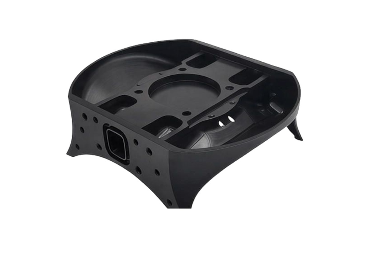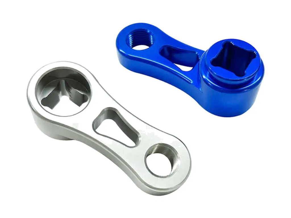


CNC Machined Aluminum Suspension Link Arm
7075-T6 aluminium suspension link arms machined from plate with bearing bores held to H7, bore-to-bore parallelism within 0.02 mm, centre length to ±0.05 mm and a tapered section that keeps the load path where the drawing puts it. Arms are machined as matched pairs and hard anodized after the bores are masked.
- Bearing Bores to H7
- Centre Length ±0.05 mm
- Tapered Section Machined
- Load Path Left Intact
*Send the bearing or bush drawing with the arm. The bore tolerance, the chamfer and the shoulder depth are all set by what goes into the eye, and a link that clamps the bush will bind in roll.
Suspension Link Arm Overview
A link arm transfers load between two points that move relative to each other, so its two bores have to stay parallel and its length has to stay fixed under load. Both are geometry problems before they are strength problems.
The arm is machined from plate with the two bores cut in the same set-up on a fixture that holds the blank by its outer profile. The tapered section is then milled from both faces, and the part is checked on the CMM for bore centres before anodizing.
7075-T6 Aluminium Plate
7075-T6 is used because a link arm is a bending member: its yield strength lets the section stay thin without the arm flexing under cornering load, which is what usually cracks an aluminium link at the eye.
6061-T6 or 6082-T6
6061-T6 is chosen for road arms where corrosion resistance and cost matter more than the last 20 % of strength. 6082-T6 is common in Europe and machines to a similar finish with a slightly lower fatigue limit.
A racing arm wants 7075 and a hard coat; a road arm is better served by 6061 and a Type II coat, because a hard coat on a part that flexes can craze at the radius.
Suspension Link Arm Specifications
Milling and boring data for link arms, with the bore, length and parallelism values that decide whether the suspension moves freely.
| Specification | Machining Data | Specification | Machining Data |
|---|---|---|---|
| Product | Suspension Link Arm / Control Arm | Machining Process | 3-Axis CNC Milling, Boring, Chamfering |
| Material | 7075-T6 Aluminium Plate | Centre-to-Centre Length | 80 – 400 mm, ±0.05 mm |
| Bearing Bore | Ø 10 – 40 mm, H7 | Bore Parallelism | 0.02 mm Between Bores |
| Arm Thickness | 8 – 20 mm, Tapered | Flatness | 0.05 mm |
| Section Width | 20 – 60 mm | Surface Finish | Ra 1.6 µm Bores, Ra 3.2 µm Flanks |
| Weight | Trimmed to Drawing ±3 % | Anodizing | Hard Anodizing 25 – 40 µm |
| Customization | Spherical Bearing Pockets, Slots, Dual-Durometer Bush Pockets | Lead Time | 6 – 8 Days Sample, 13 – 17 Days Batch |
| Inspection | CMM Bore Centres and Parallelism, Pin Gauges, Weight Check | Packing | Pair-Matched, Foam Cradle, Carton |
Key Features of Our Link Arms
Bores from one set-up, pairs matched before coating.
Both Bores in One Set-up
The two eyes are bored without moving the part, holding parallelism to 0.02 mm, so the arm does not preload the bushings when the suspension moves.
Centre Length Held to ±0.05 mm
Length is set from the finished bores rather than the blank, which keeps a pair of arms the same length and stops the car sitting at an angle.
Taper Follows the Load
The section is milled to a taper rather than left as a constant slab, which removes weight from the unloaded end and keeps the eye radius thick where the stress concentrates.
Pairs Matched and Marked
Left and right arms are machined as a pair, weighed against each other and marked, so a set goes on the car with equal geometry and equal mass.
Link that has to keep its geometry under load?
Surface Finishes for Link Arms
The bores are fits and the outside is a wear surface, so they are finished differently.
| Finish | Main Purpose | Finish | Main Purpose |
|---|---|---|---|
| Hard Anodizing | Wear resistance where the arm sees stone chips | Type II Anodizing | Colour coding left and right arms |
| Masked Bores | Keeps bearing seats at H7 after coating | Bead Blasting | Even matte before dye |
| Laser Marking | Part number and left/right on the arm face | PTFE Coating | Dry-running bearing pockets on off-road arms |
*Hard anodizing adds 25 to 40 µm and makes the surface brittle in bending. Arms that flex are usually Type II anodized with the bores masked, not hard coated.
Put your CNC milling parts into production today
All information and uploads are secure and confidential.
Trusted for Precision CNC Machined Components
Supporting OEM projects with accurate machining, flexible production, and reliable component quality.
Trusted for Precision CNC Milling.
Machining Process for Link Arms
Both bearing bores are cut in one set-up, so the arm does not fight the shock when the suspension compresses through its travel.
01. Bush and Geometry Review
Check the bush or bearing drawing against the eye, confirm the centre length and the left/right handedness before the blank is cut.
02. Profile the Blank
Machine the outer profile and the fixture lands first, so the part can be held by its outline for the boring operation without clamping on a finished face.
03. Bore Both Eyes
Bore both eyes in one set-up with a boring head, check the centre distance and parallelism on the CMM, and correct before the taper is cut.
04. Mill the Taper
Milling both faces to the tapered section, keeping the eye radius at full thickness and blending the transition so there is no stress step.
05. Anodize, Match and Pack
Mask the bores, anodize, weigh and match the pair, mark left and right and pack in a foam cradle so the bores cannot knock together.
Send the arm drawing with the bush it carries, and we will quote it as a matched pair with the bores checked for parallelism.
Suspension Link Arm FAQs
0.02 mm when both are bored in one set-up. Arms bored in two operations typically show 0.08 mm, which is enough to make a poly bush bind at full droop.
Because a left and right arm that differ in length or mass make the car sit unevenly and load one side of the anti-roll bar. Pairs are cut from the same plate and matched by weight.
No, arms ship bare with masked bores. Pressing is done at assembly so the bush preload and the alignment are controlled by the person fitting them.
It makes the surface layer brittle, which matters on a part that flexes. For a flexing arm we recommend Type II anodizing with masked bores rather than a hard coat.
Ø 10 mm H7 with a 12 mm wall around it. Below that the boring bar deflects and the bore goes tapered, so a smaller eye is reamed instead and the tolerance opens to H8.
Typically 15 to 25 % against a constant-section blank, by tapering the unloaded half and pocketing between the eyes, without changing the eye wall thickness.
Other CNC Machined Mechanical Components
Explore additional precision CNC machined components manufactured for OEM applications and customized production needs.
Precision CNC machined stainless steel control valve bodies with lapped sealing faces and gauged ports.
Custom CNC machined steel hydraulic connectors and adapters for 350 bar systems.
Custom CNC machined aluminium brackets for textile machinery and automation frames.
Custom CNC machined aluminium cavity bases for automation and electronic equipment.
Explore CNC milled clutch levers in 6061 or 7075 aluminum, built for smooth pivot movement, accurate fit, comfortable control,.
Get high‑quality machined parts in as fast as 4 days with our expanded automated CNC milling!