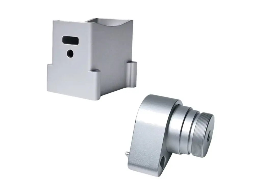


CNC Machined Aluminum Sensor Housing Block
Sensor housing blocks milled from 6061-T6 solid, with a cavity floor flat to 0.02 mm, a cap bore held to H7 and round within 0.015 mm, M3 screw holes at ±0.05 mm and a gasket groove cut to ±0.03 mm in width. The block and cap are machined as a pair and match marked before anodizing.
- Pocket Floor Flat to 0.02 mm
- H7 Bore, Round to 0.015 mm
- M3 Holes at ±0.05 mm
- Gasket Groove ±0.03 mm
*Tell us the sensor body diameter and the cable gland thread. A cavity cut 0.2 mm shallow will stop the lid seating on the gasket, and the leak only shows up after the unit is potted.
Aluminium Sensor Housing Block Overview
An inductive or photoelectric sensor needs three things from its housing: the sensing face at a fixed distance from the mounting datum, a cavity deep enough for the body plus its connector, and a lid that seals without distorting the block.
The block is squared on all six faces, the cavity is roughed and then finished with a 10 mm end mill on a 0.3 mm step-over, the cap bore is bored rather than interpolated, and the gasket groove is cut last so the sealing face is not disturbed by clamping.
6061-T6 Aluminium
6061-T6 gives a stable cavity floor after machining, anodizes to a uniform 15 to 20 µm and keeps a 90 mm block under 260 g, which matters when the sensor is carried on a robot wrist.
6082-T6 or 5052
6082-T6 is chosen when the block is welded to a bracket, and 5052 is used for covers that are formed rather than milled, since it takes a bend without cracking at the anodized edge.
Below a 3 mm wall the screw bosses pull the cavity floor convex when the lid is torqued, and the sensor no longer sits at the depth it was set to.
Sensor Housing Block Specifications
Milling and boring data for sensor bodies, with the cavity, bore and sealing values that decide whether the lid closes on the gasket.
| Specification | Machining Data | Specification | Machining Data |
|---|---|---|---|
| Product | Sensor Housing Block and Cap | Machining Process | 3-Axis CNC Milling, Boring, Facing |
| Material | 6061-T6 Aluminium | Envelope | Body 90 × 70 × 55 mm, Cap Ø 42 mm |
| Cavity | Depth ±0.02 mm, Floor Flatness 0.02 mm | Bore | H7, Roundness 0.015 mm |
| Wall Section | 3.5 mm Minimum Under the Screw Bosses | Screw Holes | M3 × 0.5, Position ±0.05 mm |
| Sealing Face | Flatness 0.03 mm, Ra 1.6 µm | Gasket Groove | Width ±0.03 mm, Depth ±0.02 mm |
| Dowel Holes | Ø 4 H7, ±0.01 mm | Edge Break | 0.3 mm, No Burr Inside the Cavity |
| Weight | 210 – 260 g per Set | Coating Build | 15 – 20 µm Anodizing |
| Customization | Cable Gland Thread, Lid Style, Port Position, Logo | Lead Time | 5 – 7 Days Sample, 12 – 16 Days Batch |
| Inspection | CMM on Cavity and Bore, Thread Plug Gauge, Air Leak Test | Packing | Bagged Individually, Foam Tray |
What Makes These Housings Repeatable
One set-up for the cavity and the bore, match-marked pairs, sealed before shipping.
Cavity and Bore From One Set-up
The block is held once and both the cavity and the cap bore are cut before unclamping, so the bore axis stays parallel to the cavity wall within 0.02 mm and the cap does not fight the body.
Gasket Groove Cut Last
The groove is machined after the sealing face is finished, using a 2 mm slot drill in a single pass; recutting it after anodizing would break the coating edge and start a leak path.
Screw Bosses Supported
Each M3 boss is tied into a 3.5 mm wall with a 1.5 mm fillet, which stops the boss from leaning when the lid screws are taken to 0.6 Nm on a repeated basis.
Block and Cap Kept as a Pair
Both halves are marked with the same serial and packed together; a cap swapped from another block will usually need the groove re-cut because the bore centres differ by a few hundredths.
Housing that has to seal on the first build?
Surface Finishes for Sensor Housings
The outside is cosmetic, the cavity is functional, and the two are finished to different rules.
| Finish | Main Purpose | Finish | Main Purpose |
|---|---|---|---|
| Clear Anodizing | General corrosion protection, machined faces visible | Black Anodizing | Optical and machine-tool sensor covers |
| Hard Anodizing | Wear face where the lid slides on | Bead Blasting | Even matte before anodizing |
| Chromate Conversion | Conductive body for an earthed sensor | Laser Marking | Part number and axis arrow |
| Masked Sealing Face | Groove stays bare so the gasket seats | Thread Masking | Gland thread stays at gauge size |
| Sealing Test | 0.3 bar air, no drop over 60 s | Lid Flatness | 0.03 mm after coating |
| Salt Spray | 500 h on 6061 after anodizing | Coating Thickness | Measured on Three Faces |
*Anodizing builds 15 to 20 µm per face; if the groove is masked after coating instead of before, the gasket sits 0.02 mm high and the lid rocks on the screws.
Put your CNC milling parts into production today
All information and uploads are secure and confidential.
Trusted for Precision CNC Machined Components
Supporting OEM projects with accurate machining, flexible production, and reliable component quality.
Trusted for Precision CNC Milling.
How We Machine a Sensor Housing
The cavity and the cap bore are cut from the same set-up, so the sensor sits square in the housing instead of being shimmed at the lid.
01. Sensor and Gland Review
Check the sensor body diameter, the connector length and the gland thread, then set the cavity depth so the sensing face lands at the drawing datum.
02. Square the Block
Face all six sides on a vice with soft jaws, leaving 0.3 mm on the cavity face for the finish pass and marking the datum corner.
03. Rough and Finish the Cavity
Rough with a 10 mm end mill at 0.5 mm step-down, then finish at 0.3 mm step-over; the floor is spring-passed to remove the tool deflection left in the corners.
04. Bore the Cap and Drill the Pattern
Bore the cap seat in the same clamping, then drill and tap the M3 holes and ream the Ø4 dowel holes from the same datum so lid and body interchange.
05. Groove, Deburr, Anodize
Cut the gasket groove, deburr every cavity edge by hand, mask the sealing face and groove, anodize, then leak test at 0.3 bar.
Send the sensor datasheet and the gland thread, and we will quote a matched block and cap with the cavity depth set from your sensing distance.
Sensor Housing Block FAQs
Yes, from the sensor drawing or a sample. The two dimensions that matter are the body diameter and the distance from the sensing face to the mounting flange, since the cavity depth is set from that second number.
Up to 3 mm deep and 1.5 to 4 mm wide with a slot drill. Deeper than 3 mm the tool needs a relieved shank, and the groove is usually split into two passes to stop the wall springing.
It adds 8 to 10 µm per wall, so an H7 bore becomes roughly an H8 after coating. Where the bore locates a bearing or a sensor body we mask it, or bore it 0.02 mm under and let the coating bring it back.
Every housing is plugged and pressurised to 0.3 bar for 60 seconds with the lid fitted. A machined groove that is 0.02 mm shallow will pass a visual check and fail this test.
3.5 mm under the screw bosses and 2.5 mm elsewhere for a 90 mm block. Thinner walls machine faster but the cavity goes convex as soon as the lid is tightened.
Yes, and it is often cheaper to buy the pair, because the cap bore and the block cavity are cut in one set-up; a block on its own needs a second clamping and the bore centre moves slightly.
Other CNC Machined Mechanical Components
Explore additional precision CNC machined components manufactured for OEM applications and customized production needs.
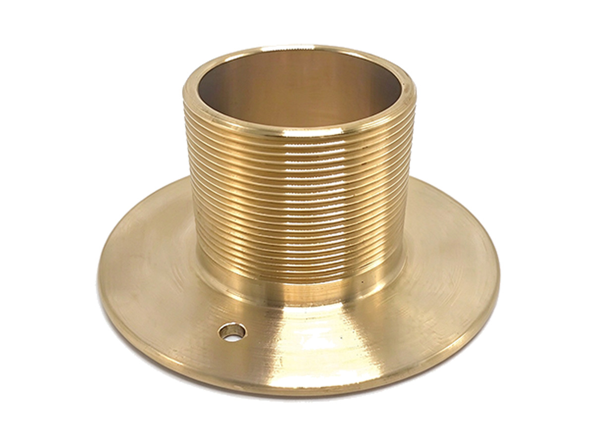
CNC turned C36000 brass threaded flange bushings with a rolled external thread, a H7 bore and a flange face square to the thread.
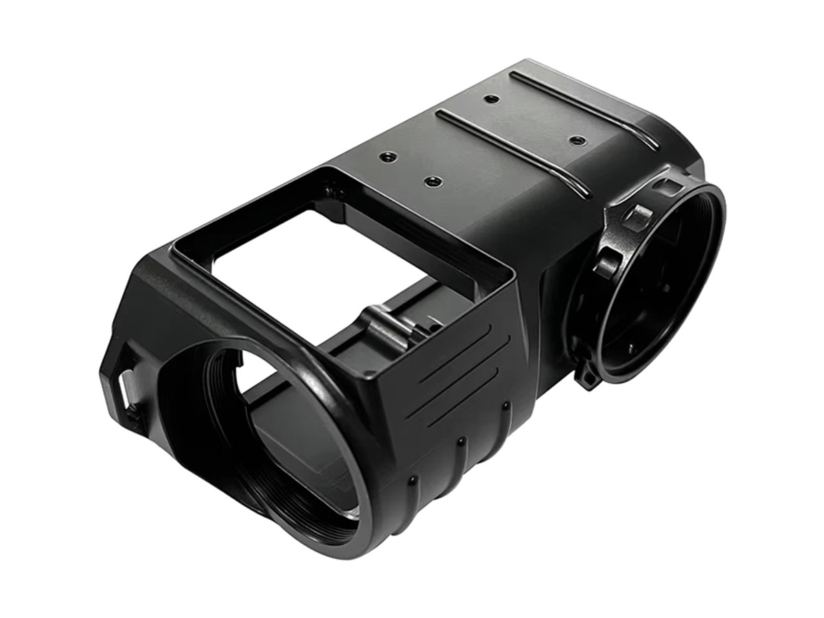
CNC machined 6061-T6 aluminium sensor enclosures with 3 mm walls, a H7 lens bore coaxial to the mount, an IP67 gasket land and.
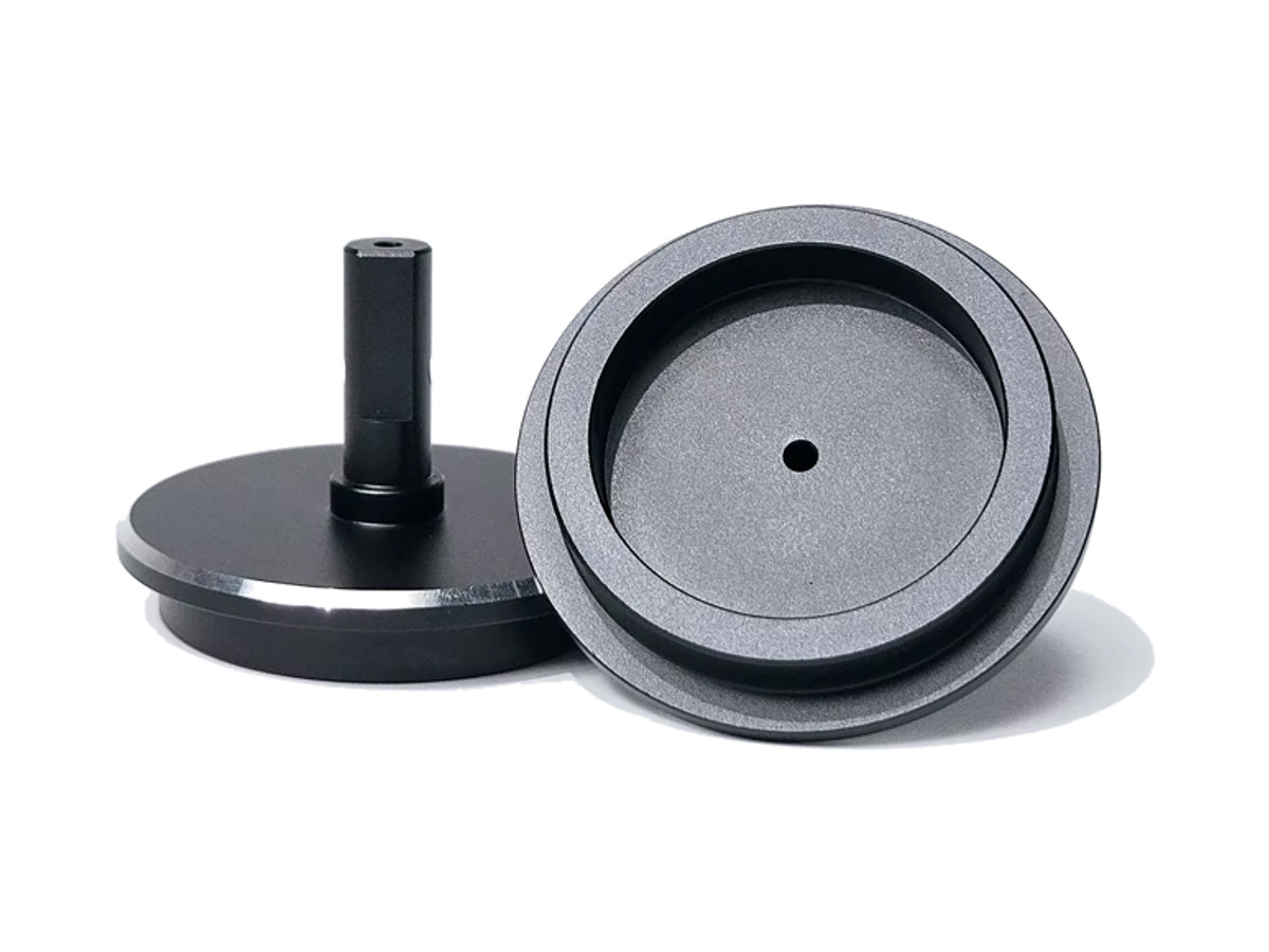
CNC turned 6061-T6 aluminium valve discs with a lapped seat face, a guided stem and a chamfered edge, held to 0.01 mm and.
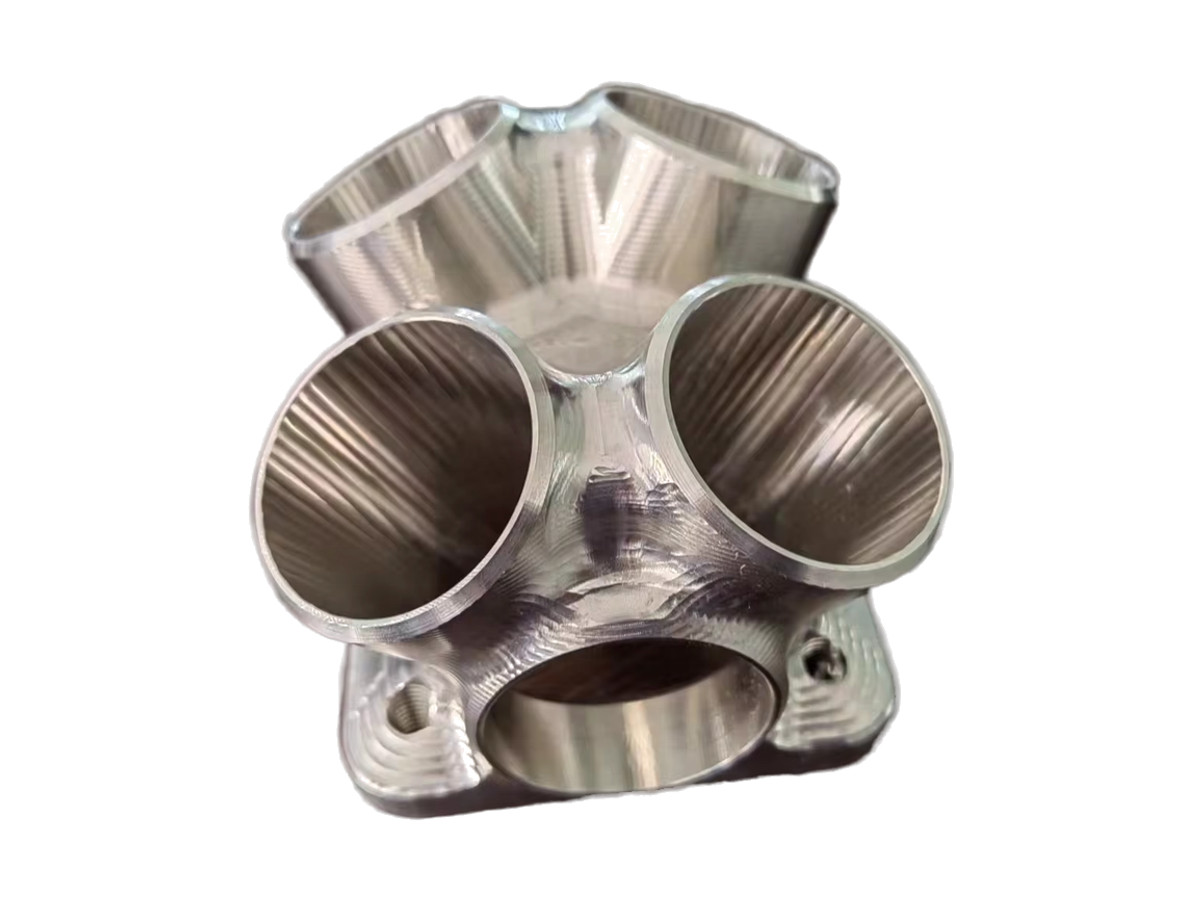
Five-axis CNC machined stainless steel spider hubs with four curved lobes, compound-angle bores and a central spline, held to.
CNC machined 6061-T6 aluminium gearbox end housings with a bearing bore to H7, a lapped seal face and a dowelled joint face,.
Get high‑quality machined parts in as fast as 4 days with our expanded automated CNC milling!