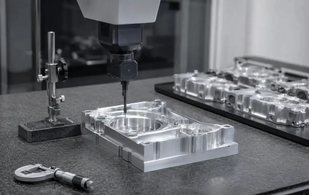


CNC Machined Aluminum Fixture Plate
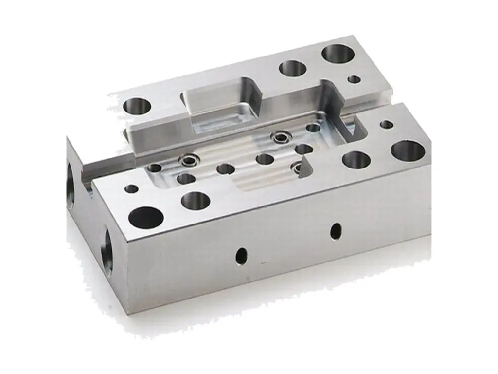
Fixture and tooling plates machined from 6061-T6, flat to 0.02 mm over 300 mm, parallel to 0.03 mm, with an M6 or M8 grid at ±0.01 mm, counterbores at ±0.05 mm depth and dowel holes reamed to H7 for repeatable set-ups.
- Flat to 0.02 mm Over 300 mm
- Hole Grid at ±0.01 mm
- Seats Cut in One Set-up
- Stress Relieved Before Finish
*Send the machine table pattern and the fixture footprint. A plate drilled on a 50 mm grid rarely matches a 40 mm table, and an adapter plate costs more than cutting the right grid first time.
Aluminium Fixture Plate Overview
A fixture plate is a flat reference with a hole pattern in it. Every part clamped to it inherits the plate flatness, so a plate that bows 0.05 mm makes every part on the machine 0.05 mm out.
The blank is faced both sides, rough machined, stress relieved at 180 °C, then finished and the grid drilled from one datum corner. Flatness is mapped on a granite plate after coating, not before.
6061-T6, 20 – 40 mm
6061-T6 at 25 mm gives a stiff plate that does not deflect under clamp load and machines to a stable grid. It is the usual choice for vacuum and modular fixtures up to 600 mm long.
7075-T6 or Cast Tooling Plate
7075-T6 is used where the plate is thin and the clamp loads are high, and cast tooling plate is chosen when a large plate has to stay flat without stress relief, at the cost of a softer thread.
Below 20 mm the plate deflects between the clamping points and the flatness is only as good as the table underneath it; above 40 mm the weight needs lifting points.
Fixture Plate Specifications
Facing, drilling and inspection data for tooling plates, with the flatness and grid values that keep set-ups repeatable.
| Specification | Machining Data | Specification | Machining Data |
|---|---|---|---|
| Product | Fixture Plate / Tooling Base Plate | Machining Process | 3-Axis CNC Milling, Drilling, Facing |
| Material | 6061-T6 Aluminium, 20 – 40 mm | Envelope | Up to 600 × 400 mm |
| Flatness | 0.02 mm Over 300 mm | Parallelism | 0.03 mm Between Faces |
| Hole Grid | M6 / M8 on 25, 40 or 50 mm Pitch | Grid Position | ±0.01 mm |
| Counterbores | Depth ±0.05 mm, Flat Seat | Dowel Holes | Ø 8 H7, ±0.01 mm |
| T-Slots | Width +0.05 / 0 mm, Straight 0.02 mm/m | Edge Break | 0.5 mm, Chamfered All Round |
| Thickness | ±0.05 mm | Weight | 6 – 14 kg per Plate |
| Customization | Grid Pitch, Vacuum Grooves, Lifting Holes, Sub-Plate Pattern | Lead Time | 6 – 8 Days Sample, 12 – 18 Days Batch |
| Inspection | Granite Flatness Map, CMM Grid, Thread Plug Gauges | Packing | Wooden Crate, Face Film, Corner Guards |
Key Features of Our Fixture Plates
Stress relieved between roughing and finishing, grid from one datum, flatness mapped after coating.
Rough, Relieve, Finish
The plate is roughed, heated to 180 °C for four hours and finish machined afterwards, which removes the surface stress that makes an as-machined plate bow 0.1 mm overnight.
Grid From One Datum Corner
Every hole is positioned from the same corner rather than stepped from the previous hole, so the error does not accumulate across a 600 mm plate.
Counterbores Cut With the Grid
Seats are cut in the same set-up as the holes, so a bolt sits flat and the clamp does not cock when it is tightened on one side.
Flatness Checked After Coating
Anodizing pulls a thin plate by a few hundredths, so the plate is mapped on a granite surface plate after coating and the result ships with it.
Plate that has to stay flat under clamps?
Surface Finishes for Fixture Plates
The top face is the reference, the grid is the interface, the edge is handling.
| Finish | Main Purpose | Finish | Main Purpose |
|---|---|---|---|
| Clear Anodizing | Wear surface without changing the grid | Hard Anodizing | Heavy clamping, 40 µm build |
| Chromate Conversion | Conductive plate for earthing fixtures | Masked Holes | Grid stays at gauge size |
| Bead Blasting | Even matte between the holes | Laser Marking | Grid coordinates on the edge |
| Face Film | Protects the lapped face in transit | Rust Preventive | Steel sub-plate interface |
| Flatness Recheck | Measured after coating, not before | Crate Support | Plate supported on three points |
| Salt Spray | 500 h on 6061 | Grid Recheck | Holes and Threads After Coating |
*Hard anodizing builds 40 µm and closes an M6 thread by about 0.08 mm on diameter; threads are masked or chased after coating, never left to the customer.
Put your CNC milling parts into production today
All information and uploads are secure and confidential.
Trusted for Precision CNC Machined Components
Supporting OEM projects with accurate machining, flexible production, and reliable component quality.
Trusted for Precision CNC Milling.
Machining a Fixture Plate
The plate is roughed, stress relieved and then finished, so it stays flat after the grid is cut instead of bowing as the pockets release the surface stress.
01. Table and Fixture Review
Check the machine table pattern, the fixture footprint and the clamp positions, then set the grid pitch and the plate thickness from the load.
02. Face and Rough
Face both sides, rough the counterbores and slots leaving 0.3 mm, and mark the datum corner on the edge with a stamped number.
03. Stress Relieve
Heat the plate to 180 °C, hold for four hours and cool in the oven, which releases the stress that would otherwise bow the finished plate.
04. Finish and Drill
Finish both faces, drill and ream the grid from the datum corner, cut the counterbores and T-slots, then chamfer every edge at 0.5 mm.
05. Coat, Map, Crate
Mask the threads, anodize, re-check the grid with plug gauges, map flatness on granite and crate the plate on three support points.
Send the table pattern and the fixture drawing, and we will quote a plate with the grid cut from one datum and the flatness measured after coating.
Fixture Plate FAQs
0.03 mm over the full length after stress relief, and 0.02 mm over 300 mm. Without the relief cycle the same plate moves 0.1 mm within a day of machining.
Yes, from the table drawing or a measured pattern. We cut to the measured positions on an existing machine, which is usually not the nominal pitch after years of use.
M8 on a 50 mm grid for general work, with stainless inserts if the plate is re-clamped daily. A bare M6 thread in 6061 will strip after a few hundred cycles at full torque.
Yes, grooves are cut 1.5 mm wide by 1 mm deep with an O-ring cord seat around the perimeter, and the vacuum port is drilled from the edge.
By 0.01 to 0.03 mm on a 20 mm plate, which is why the plate is mapped after coating. Thicker hard anodizing moves it more and is only used where wear matters.
In a crate, standing on three support points with the face filmed and corner guards fitted, so it does not take a set from being laid flat on a pallet.
Other CNC Machined Mechanical Components
Explore additional precision CNC machined components manufactured for OEM applications and customized production needs.
CNC turned brass spray nozzles with a tapered internal bore, a drilled orifice from 0.3 mm and a threaded body, flow tested and.
CNC turned 316L stainless steel valve seat spools with ground sealing diameters, square shoulders and lapped seat faces, round to.
CNC machined 6061-T6 aluminium enclosure base plates with a pocketed floor, sealed gasket land, blind standoffs and edge screw.
CNC turned 316L stainless sleeve bushings with a heavy wall, a bore to H7 and square ends, machined from bar for pump, valve and.
CNC machined 7075-T6 aluminium suspension link arms with bearing bores to H7, centre-to-centre length to ±0.05 mm, tapered.
Get high‑quality machined parts in as fast as 4 days with our expanded automated CNC milling!