

Five-Axis CNC Machined Aluminum Vacuum Pump Impeller
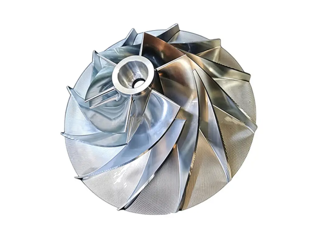
Vacuum pump impellers machined on five axes from 7075-T6, with 9 swept blades cut to the CFD surface within 0.05 mm, a 1.5 mm trailing edge, a H7 bore square to the back face within 0.02 mm and balance to G2.5 at 8,000 rpm.
- 9 Blades Cut in One Set-up
- Trailing Edge 1.5 mm
- Bore H7 to the Back Face
- Balanced to G2.5
*Send the CFD surface and the housing bore, not a 2D section. The tip clearance is set by the housing, and an impeller machined 0.1 mm under size loses more flow than a change of blade angle.
Vacuum Pump Impeller Overview
An impeller is a flow part and a balance part at the same time: the blade surface decides the vacuum, the tip clearance decides the leakage, and the mass distribution decides whether the bearing survives 8,000 rpm.
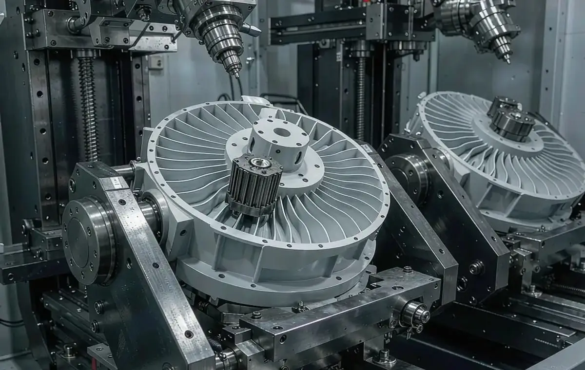
The billet is turned to the hub and back face, rough machined between the blades on five axes, stress relieved, then finished from hub to tip in one continuous pass before boring and balancing.
7075-T6 Aluminium Billet
7075-T6 is used because the blades are thin and see a bending load at every start. It also machines to a clean 0.8 µm surface on a swept surface, which is what keeps the boundary layer attached.
6061-T6 or 2618-T6
6061 is used for low-speed impellers where corrosion resistance matters more than strength, and 2618 forgings for hot-air or high-temperature duties where 7075 loses strength above 120 °C.
For a tip speed above 150 m/s the blade material and the balance grade matter more than the surface finish; below that, a 0.8 µm finish is worth more than another 0.02 mm of profile accuracy.
Vacuum Pump Impeller Specifications
Five-axis machining data for impellers, with the blade, bore and balance values that decide whether the pump reaches its curve.
| Specification | Machining Data | Specification | Machining Data |
|---|---|---|---|
| Product | Vacuum Pump Impeller / Semi-Open Rotor | Machining Process | 5-Axis Simultaneous CNC Milling, Boring |
| Material | 7075-T6 Aluminium Billet | Envelope | Ø 80 – 320 mm |
| Blade Count | 6 – 12 Blades, Evenly Indexed | Blade Thickness | 1.5 – 4 mm at the Tip |
| Blade Profile | Swept, Machined to the CFD Surface ±0.05 mm | Tip Clearance | 0.15 – 0.30 mm |
| Bore | Ø 15 – 50 mm, H7 | Bore to Back Face | Square 0.02 mm |
| Back Face Flatness | 0.02 mm | Hub Diameter | Ø 40 – 120 mm |
| Balance | G2.5 at 8,000 rpm | Surface Finish | Ra 0.8 µm on the Blades |
| Customization | Splitter Blades, Back Vanes, Keyway, Clamping Nut Thread | Lead Time | 8 – 10 Days Sample, 18 – 25 Days Batch |
| Inspection | CMM Blade Profile, Bore Air Gauge, Balance Report, Runout | Packing | Blade Guard, Foam Cradle, Individually Boxed |
Key Features of Our Impellers
Blades finished in one pass, bored from the back face, balanced as a finished part.
Blades Finished Hub to Tip
Each blade is finished in one continuous five-axis pass, which keeps the trailing edge at 1.5 mm instead of thinning where the tool has to stop and restart.
Rough, Relieve, Finish
The blade pockets are roughed to 1 mm, the part is stress relieved, then finished. That is what stops a 1.5 mm trailing edge from waving after the last pass.
Bore From the Back Face
The bore is cut with the back face as datum, so the impeller sits square on the shaft and the tip clearance stays even around the housing.
Balanced After Coating
Balance is measured and corrected on the finished part, with correction drilled on the hub underside where it does not disturb the flow path.
Impeller that has to hit the pump curve?
Surface Finishes for Impellers
The blade surface is an aerodynamic tolerance, the hub is a corrosion surface and the bore is a fit.
| Finish | Main Purpose | Finish | Main Purpose |
|---|---|---|---|
| Bare Machined Blades | Keeps the aerodynamic surface within tolerance | Type II Anodizing | Corrosion protection on the hub only |
| Masked Bore | Bore stays at H7 after coating | Bead Blasting | Blends the blade roots without changing profile |
| Balance Correction | Drilling on the Hub Underside | Laser Marking | Impeller serial and balance position |
| Anodizing Build | 10 – 15 µm, Hub Only | Vapour Blasting | Satin Finish Between Blades |
| Bore Plug | Fitted During Coating | Blade Protection | Sleeve Fitted for Shipping |
| Assembly Clean | Ultrasonic Before Balancing | Runout Check | Dial Indicator on the Back Face |
*Blades are left bare: anodizing builds 10 to 15 µm and would take a 1.5 mm trailing edge out of profile. The hub is masked around the blade roots so only the visible body is coated.
Put your CNC milling parts into production today
All information and uploads are secure and confidential.
Trusted for Precision CNC Machined Components
Supporting OEM projects with accurate machining, flexible production, and reliable component quality.
Trusted for Precision CNC Milling.
Machining Process for Impellers
The blades are finished in one five-axis pass from hub to tip, so the trailing edge stays 1.5 mm instead of thinning where the tool runs out of reach.
01. Surface and Housing Review
Check the CFD surface, the housing bore and the shaft fit, then set the tip clearance from the measured housing rather than the nominal drawing.
02. Turn Hub and Back Face
Turn the back face, the hub and the bore register in one set-up, establishing the datum that every blade is measured from.
03. Rough the Blade Pockets
Rough between the blades on five axes leaving 1 mm, working from the outside in so the blades stay supported as long as possible.
04. Stress Relieve and Finish
Stress relieve the part, then finish each blade from hub to tip in one continuous pass, checking thickness with an ultrasonic gauge.
05. Bore, Balance, Inspect
Finish the bore, balance to G2.5, correct on the hub underside, then CMM the blade profile and record runout on the back face.
Send the CFD surface and the measured housing bore, and we will quote an impeller with the blades cut to your flow path and balanced to G2.5.
Vacuum Pump Impeller FAQs
1.5 mm in 7075-T6 on a 200 mm impeller. Below that the edge deflects under cutting load and the finished profile waves by 0.05 mm even though the tool path was correct.
G2.5 at the working speed, corrected by drilling the hub underside. For a 250 mm impeller at 8,000 rpm that is about 1.2 g·mm of residual unbalance.
Yes, from the same surface model. Splitters are roughed with the main blades and finished in the same set-up, so the leading edge spacing stays within 0.05 mm.
From the measured housing bore, not the drawing. The impeller is machined to leave 0.15 to 0.30 mm, and a housing that is 0.1 mm over nominal would otherwise give 0.4 mm and lose vacuum.
No, blades stay bare so the profile is unchanged. The hub is anodized with the blade roots masked, and the part is cleaned ultrasonically before balancing.
If a blade is damaged the part is usually replaced, because welding changes the balance and the local heat treatment. Minor tip rubs are blended by hand and the part is rebalanced.
Other CNC Machined Mechanical Components
Explore additional precision CNC machined components manufactured for OEM applications and customized production needs.
Custom five-axis CNC machined stainless steel turbine stators and nozzle rings.
Precision CNC machined stainless steel gripper fingers for robot end effectors.
Custom CNC machined aluminum hollow L brackets with lightening cut-outs, machined in 6061-T6 or 7075-T6, flat to 0.05 mm and anodized to your colour.
Custom CNC machined aluminium motorcycle components, including clamps, covers, mounts and bearing housings.
Custom CNC machined aluminium filament stand brackets for 3D printer spool holders.
Get high‑quality machined parts in as fast as 4 days with our expanded automated CNC milling!