


Home / CNC-Machining / CNC 5-Axis Machining / Five Axis CNC Machined Aluminum Frame Segments
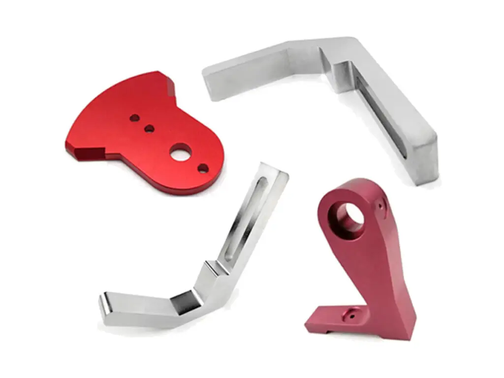
Five axis CNC machined aluminum frame segments with compound angle faces and a barrel cut blend

Five Axis CNC Machined Aluminum Frame Segments

Frame segments machined on simultaneous five-axis centres from 6061-T6, with the profile held to ±0.03 mm of the model, compound faces at ±0.05°, mating faces flat to 0.02 mm and pairs matched within 0.03 mm and packed together.

*Send the 3D model with the datum scheme, not just a 2D drawing. A compound face defined only by two views leaves the blend radius open, and the mating part will not sit flush.

Five Axis Machined Frame Segments Overview

These segments form a joint on a machine frame where two planes meet at a compound angle. The joint only closes if both faces are cut from the same set-up, because re-clamping moves the second face by a few hundredths.

The blank is roughed on three axes, then finished on a five-axis centre with a barrel cutter on the blend, so the transition from one face to the next is continuous and the corner radius matches the model.

Five-axis milling of an aluminum wrist housing for a robot arm
6061-T6 aluminium flat plate stock for CNC milling

6061-T6 Aluminium

6061-T6 is stiff enough at a 3.5 mm wall for a frame segment and anodizes evenly over a curved surface, which matters when two segments sit next to each other in different colours.

7075-T6 aluminium billet block stock for CNC milling

7075-T6 or 5083

7075-T6 is used at the pivot where the load is concentrated, and 5083 is chosen for segments that are welded into a gantry, since it keeps strength in the heat-affected zone.

Under a 3.5 mm wall the segment rings when the frame is loaded, and the anodized face shows a ripple that no amount of polishing removes.

Frame Segment Specifications

Five-axis finishing data for frame joints, with the profile and pair-match values that decide whether a joint closes.

SpecificationMachining DataSpecificationMachining Data
ProductFrame Segment Set with Compound FacesMachining Process5-Axis Simultaneous CNC Milling
Material6061-T6 Aluminium, 15 – 30 mm PlateEnvelopeUp to 260 × 120 × 60 mm
Profile±0.03 mm to the ModelCompound Angle±0.05° from the Datum
Face Flatness0.02 mm on Mating FacesWall Thickness3.5 mm Minimum
Bolt HolesM5 / M6, Position ±0.05 mmHole AxisNormal to the Local Face Within 0.2°
Pair MatchFaces Within 0.03 mm of Each OtherEdge Break0.4 mm on All Machined Edges
Weight180 – 620 g per SegmentCoating Build15 – 20 µm Anodizing
CustomizationColour, Angled Interface, Cable Channel, Pair OrientationLead Time8 – 10 Days Sample, 16 – 22 Days Batch
InspectionCMM Scan Against the Model, Pair Match Check, Thread GaugesPackingPair Bagged Together, Foam Divider

What Five-Axis Brings to These Segments

One set-up for compound faces, barrel-cut blends, pairs measured together.

Compound Faces in One Set-up

Both angled faces are finished without unclamping, so their intersection stays within 0.03 mm and the segment seats on two planes without a shim or a file.

Barrel Cutter on the Blend

The transition between the two faces is cut with a barrel cutter rather than a ball nose, which gives a continuous radius instead of a ring of scallops that shows through the anodizing.

Holes Normal to the Local Face

Bolt holes are drilled on the tilted axis so each screw seat is square to its own face within 0.2°, which stops a cap screw from pulling the joint out of line.

Pairs Machined and Checked Together

Left and right segments are cut from one blank, measured as a pair and packed together; mixing pairs from different batches leaves a 0.05 mm step at the joint.

Joint that has to close without shims?

Finishes for Frame Segments

Colour is often functional here, but the mating faces always stay bare.

FinishMain PurposeFinishMain Purpose
Clear AnodizingProtection with machined faces visibleRed AnodizingColour-coded frame segments
Black AnodizingMachine frame and gantry partsHard AnodizingWear faces at the pivot
Bead BlastingEven matte over a 5-axis surfaceMasked InterfacesMating faces stay bare
Laser MarkingSegment number and orientationColour MatchBatch-to-batch dye control
Pair CheckBoth halves measured togetherFace FilmPeel coat on mating faces
Salt Spray500 h on 6061Pair Match RecheckBoth Halves After Coating

*Anodizing builds 15 to 20 µm on every face; mating faces are masked so the joint closes on metal, not on two layers of oxide that crush unevenly.

logo

Put your CNC milling parts into production today

All information and uploads are secure and confidential.

Trusted for Precision CNC Machined Components

Supporting OEM projects with accurate machining, flexible production, and reliable component quality.

Mechanical Equipment Customer
The joint closed on both faces without a shim, which is why we went to five-axis.

Industrial Components Buyer
The left and right pair matched, so the frame is not twisted.

Equipment Manufacturer
The blend on the curved face is smooth enough to anodize without polishing.

OEM Customer
OEM Customer
The bolt seats are square, so nothing pulled the joint out of line.

Automation Industry Customer
The customized machining solution provided the dimensional accuracy required for our rotating equipment components.

Trusted for Precision CNC Milling.

Machining a Five-Axis Frame Segment

The compound faces are cut in one five-axis set-up, so the segment seats on two planes at once instead of being re-clamped and blended by hand.

01. Model and Datum Review

Read the 3D model, agree the datum scheme and identify which faces mate, then plan the set-up so no mating face needs re-clamping.

02. Rough on Three Axes

Rough the blank on a three-axis mill leaving 0.6 mm on all faces, which removes most of the material before the slower five-axis pass.

03. Finish on Five Axes

Finish the compound faces and the blend in one continuous five-axis path with a barrel cutter, keeping the tool normal to the surface throughout.

04. Drill on Tilted Axes

Drill and tap the bolt holes normal to each local face, then ream the dowel holes from the primary datum so pairs locate on the same pins.

05. Measure, Mask, Anodize

Scan the part against the model on a CMM, check the pair match, mask the mating faces, anodize and pack each pair together.

Send the 3D model and tell us which faces mate, and we will quote segments finished in one five-axis set-up with the pair matched before coating.

Five Axis Frame Segment FAQs

Because the compound angle needs two re-clampings, and each one moves the part by 0.02 to 0.05 mm. The joint then needs a shim, which is exactly what a five-axis part avoids.

±0.03 mm against the model on a scanned surface, with the compound angle within ±0.05°. Tighter than that needs the model tessellated to the same tolerance.

Yes, from a scan of the mating part. We build the model from the scanned surface rather than the nominal drawing, which is what a retrofit needs.

With a barrel cutter on a continuous path at 0.15 mm step-over, then a light bead blast before anodizing. A ball nose at the same step-over leaves visible scallops.

Eight to ten days for a sample, because the five-axis path has to be proven on the first part and the CMM scan compared with the model before the batch runs.

Yes, and they are always measured as a pair. Two right-hand segments from different batches will not close a joint to better than 0.05 mm.

Other CNC Machined Mechanical Components

Explore additional precision CNC machined components manufactured for OEM applications and customized production needs.

CNC machined aluminium perforated mounting plates with a lightening hole pattern, edge datum faces and counterbored fixings, flat.

CNC machined 6061-T6 aluminium mounting brackets with a machined mounting face, slotted holes and an even anodized finish, held.

CNC turned 6061-T6 aluminium deflector cones with a true cone angle, radial ports drilled on compound angles and an anodized.

Five-axis machined 6061-T6 aluminium rotary actuator bodies with a through bore, end flanges and ports on compound faces, bored.

304L stainless bearing support blocks with a bored bearing seat to H7, seat and base parallel to 0.02 mm, and clamp-screw flats.

Get high‑quality machined parts in as fast as 4 days with our expanded automated CNC milling!

Scroll to Top