

Five-Axis CNC Machined Aluminum Cradle Bracket
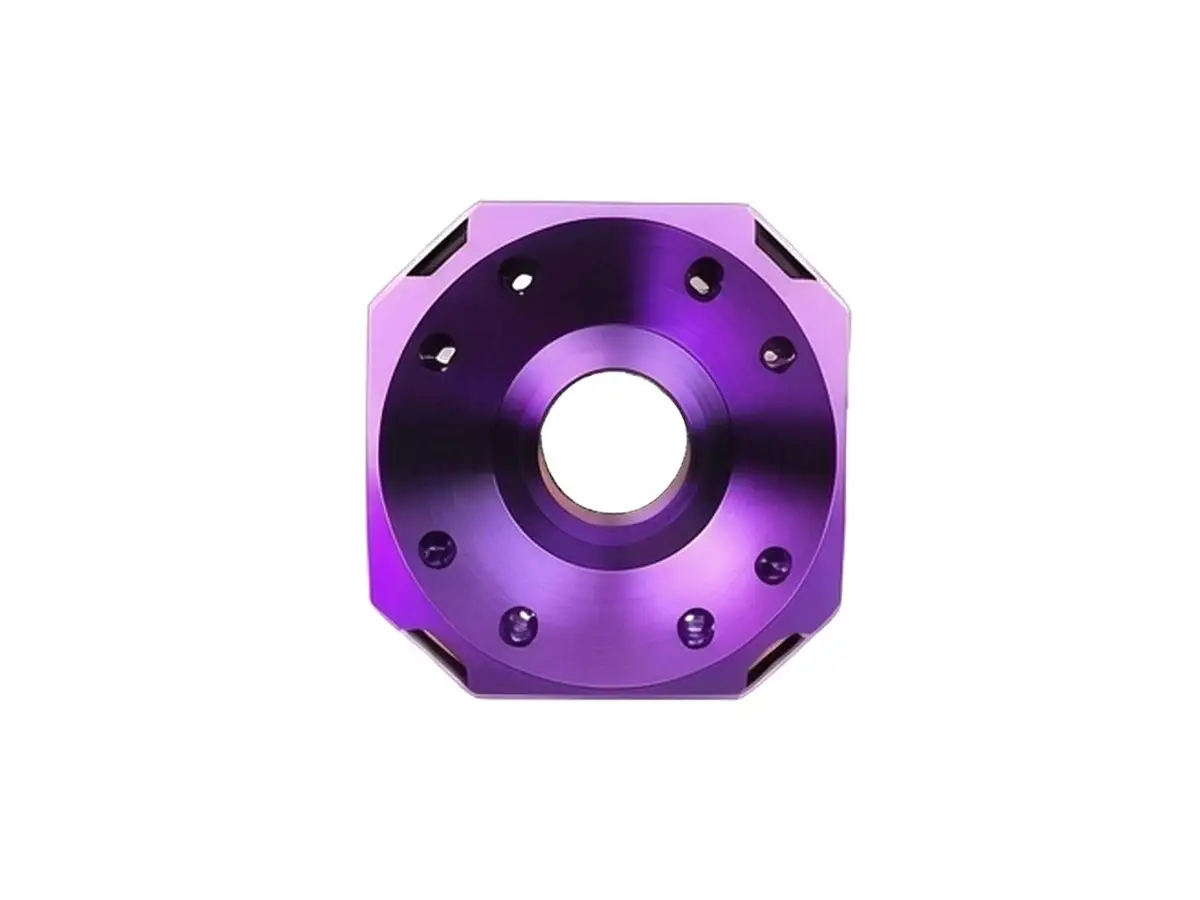
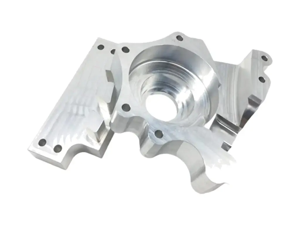
Cradle brackets five-axis machined from 7075-T6 billet, with swept arms held to a 3 mm wall, four mounting pads coplanar to 0.03 mm at angles up to 45°, bores positioned to ±0.05 mm and lightening pockets trimmed to within 3 % of the model mass. Machined in one set-up so there is no joint line across the sweep.
- Pads Coplanar 0.03 mm
- Swept Arms Without Facets
- Pockets Cut to 2.5 mm Wall
- One Set-up, No Joint Lines
*Send the model, not a 2D drawing. The value of this part is the sweep and the pad angles, and a drawing cannot define either well enough to machine from.
Cradle Bracket Overview
A cradle bracket ties two pick-up points together across a gap and does it at an angle. The pads have to be coplanar, the arms have to carry load without a stress concentration and the whole part has to be light enough to be worth machining from billet.
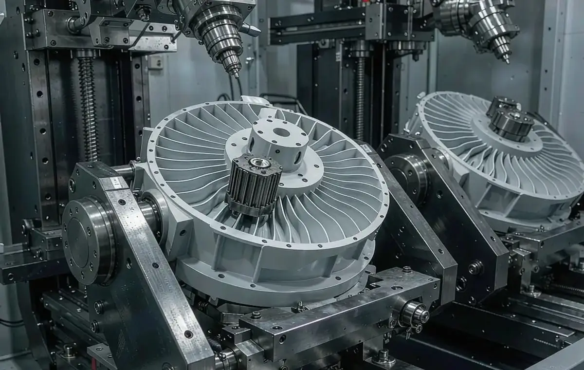
Five-axis machining lets the pads and the bores be cut without reclamping, so their relationship comes from the machine rather than from a fixture. The sweep is cut with a ball-nose tool at a fine step-over, then the pockets are opened from the inside to leave a constant wall.
7075-T6 Aluminium Billet
7075-T6 is chosen for strength per kilogram: a 3 mm wall in 7075 carries what a 5 mm wall in 6061 carries. It also machines to a sharper edge, which matters where the arm sweep meets the pad.
6061-T6 or 6082-T6
6061 is used on brackets that are not load-critical, where the extra wall thickness costs less than the billet. 6082 is the European equivalent and welds if a bracket has to be modified in service.
Above about 250 mm span the bracket is usually redesigned in 7075 with a deeper section rather than made thicker in 6061, because stiffness grows with the cube of depth.
Cradle Bracket Specifications
Five-axis data for swept brackets, with the pad, bore and wall values that decide whether the part fits and survives.
| Specification | Machining Data | Specification | Machining Data |
|---|---|---|---|
| Product | Cradle Bracket / Swept Support Bracket | Machining Process | 5-Axis CNC Milling, Drilling, Tapping |
| Material | 7075-T6 Aluminium Billet | Envelope | Up to 420 × 320 × 160 mm |
| Mounting Pads | Coplanar 0.03 mm, Angled Up to 45° | Pad Flatness | 0.02 mm per Pad |
| Hole Position | ±0.05 mm Between Pads | Arm Wall | 3 – 6 mm |
| Pocket Floor | ±0.05 mm, Corner Radii Matched to Tool | Bore Diameter | Ø 8 – 40 mm, H7 |
| Surface Finish | Ra 1.6 µm Machined, Ra 0.8 µm Bores | Weight | Trimmed to ±3 % of Model Mass |
| Customization | Cable Clips, Sensor Pads, Extra Lightening Pockets | Lead Time | 7 – 9 Days Sample, 14 – 18 Days Batch |
| Inspection | CMM Pad Plane and Hole Position, Mass Check, Wall Ultrasonic | Packing | Foam Nest, Individually Bagged, Crate |
Key Features of Our Cradle Brackets
Swept in one set-up, pads coplanar.
Pads Cut Without Reclamping
All four pads are machined from one datum, so they stay coplanar to 0.03 mm even when they sit at different angles.
Sweep Cut at Fine Step-over
The arm is finished with a 0.3 mm step-over on a ball-nose cutter, which removes the facets that would otherwise become crack starters.
Constant Wall From Inside Out
Pockets are opened from the inside so the wall stays at 3 mm, instead of being thinned where two pockets meet near the outside.
Mass Trimmed to the Model
Each bracket is weighed against the model and trimmed before anodizing, keeping the corner weights the chassis was set up for.
Bracket that has to be light and stiff?
Surface Finishes for Cradle Brackets
Pads and bores are fits; the rest of the bracket is a handling and corrosion surface.
| Finish | Main Purpose | Finish | Main Purpose |
|---|---|---|---|
| Hard Anodizing | Wear and corrosion on a part that is handled every pit stop | Type II Anodizing | Colour coding by corner of the car |
| Masked Pads | Keeps mounting pads at nominal height | Bead Blasting | Even matte before dye |
| Laser Marking | Corner number and datum arrow | Bare Bores | Conductive bores used for grounding |
*Hard anodizing adds 25 to 50 µm and would lift the pads off the plane. Pads and bores are masked, and the coating is kept off any face that carries a bolted joint.
Put your CNC milling parts into production today
All information and uploads are secure and confidential.
Trusted for Precision CNC Machined Components
Supporting OEM projects with accurate machining, flexible production, and reliable component quality.
Trusted for Precision CNC Milling.
Five-Axis Machining Process
The arms sweep instead of stepping, so the bracket carries the load in tension rather than through a row of stress-raising corners.
01. Model and Load Review
Check the pad positions, the bore sizes and the load path in the model, and confirm which faces must stay bare for bolted joints.
02. Rough From Billet
Rough the outside and the pockets with a 16 mm cutter, leaving 0.6 mm on all surfaces so the part can settle before finishing.
03. Semi-Finish and Stress Relief
Semi-finish the sweep and release the part from the vice, allowing the internal stress to move it before the finish passes.
04. Finish Pads and Bores
Finish the pads in one continuous pass, bore the holes and check the pad plane on the CMM before the part leaves the machine.
05. Weigh, Anodize, Inspect
Weigh against the model, adjust the pockets if needed, mask the pads and bores, hard anodize and CMM the final part.
Send the model and the load case, and we will quote a bracket with the pads coplanar and the arms swept without facets.
Cradle Bracket FAQs
A fabricated bracket has welds at exactly the points where the bending load peaks. A billet bracket keeps the grain continuous through the sweep and removes the weld inspection step.
0.03 mm across all pads, even when they sit at different angles, because they are machined in one set-up. After hard anodizing they are re-checked with the pads masked.
3 mm on a bracket up to 300 mm span. Below that the wall deflects during finishing and the part rings in service.
Yes, the second hand is a mirrored programme, machined from the same billet size so the pair matches in mass and stiffness.
The model mass is the target, and each part is weighed before anodizing. Pockets are adjusted in 0.5 mm steps until the part is within 3 % of the target.
Yes, on critical sections with an ultrasonic gauge, because a thin wall from a deep pocket is not visible on a CMM and is the usual cause of a bracket cracking in service.
Other CNC Machined Mechanical Components
Explore additional precision CNC machined components manufactured for OEM applications and customized production needs.
Custom CNC machined aluminium drone components, including arm mounts, motor mounts and frame fittings.
Custom CNC machined aluminium robot joint actuator components with concentric threads, sealing faces and hex flats.
Custom CNC machined robot end effector flanges for tool mounting and automation.
Custom Brake Lever CNC Milled components manufactured with precision CNC machining, supporting OEM customization, lightweight.
CNC machined aluminium robot mounting brackets supplied as matched pairs, right-angle held to 0.05 mm, gusseted for stiffness and.
Get high‑quality machined parts in as fast as 4 days with our expanded automated CNC milling!