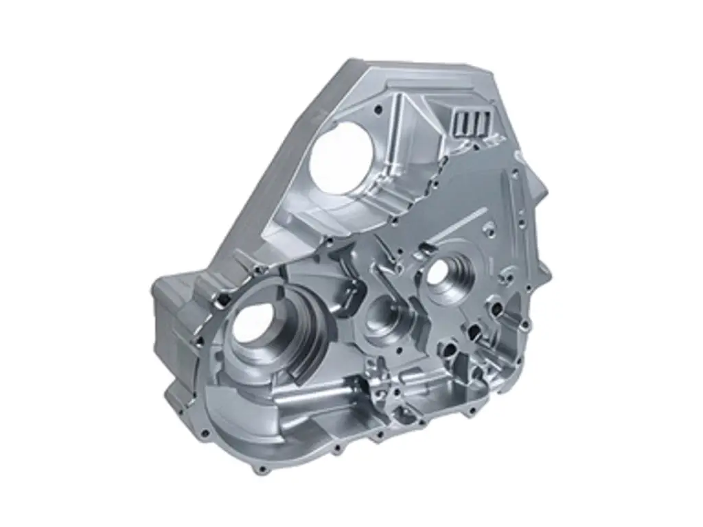


CNC 5-Axis Machined Motorcycle Engine Cover
Engine side covers machined on five simultaneous axes from 6061-T6: 260 × 210 × 65 mm, 2.5 mm walls held to ±0.05 mm, a Ø35 H7 bearing bore round within 0.012 mm, a sealing face flat to 0.03 mm and sculpted ribs blended with R3 fillets. The cover is pressure tested at 0.5 bar before finishing and the sealing face is masked through anodizing.
- Wall 2.5 mm ±0.05
- Bearing Bore H7
- Sealing Face 0.03
- Sculpted on 5 Axes
*Send the crankcase gasket and the bearing drawing. A sealing face that is 0.05 mm out will leak at the front edge once the engine is hot, and the wall thickness decides how much the cover rings.
Five-Axis Engine Cover Overview
An engine cover is a thin shell with a precise face and a bearing bore. The outside is sculpted for style and stiffness, the inside has to clear the clutch or the alternator, and the two have to meet at a 2.5 mm wall that does not distort when the cover bolts are torqued.
The cover is roughed on three axes, then finished on five simultaneous axes so the outer sculpt and the inner clearance are cut in one continuous path without re-fixturing. The bearing bore is bored after the shell is finished, and the sealing face is cut last so nothing deflects it afterwards.
6061-T6 Aluminium
6061-T6 lets the cover be machined to a 2.5 mm wall and still hold a bearing bore, and it takes a polished anodized finish that a cast cover cannot reach.
6082-T6 or A356 Casting
6082-T6 is used where the cover is welded for a repair, and A356 is chosen for higher volumes where a casting is machined only on the face and bore.
A wall under 2 mm will drum at engine speed and the sealing face will move; the wall is held at 2.5 mm and ribs are added where the panel is largest.
Five-Axis Engine Cover Specifications
Wall, bore and sealing values, plus the pressure test that proves the shell is sound.
| Specification | Machining Data | Specification | Machining Data |
|---|---|---|---|
| Product | Motorcycle Engine Side Cover | Process | 5-Axis Simultaneous Milling, Boring |
| Material | 6061-T6 Aluminium | Envelope | 260 × 210 × 65 mm |
| Wall Thickness | 2.5 mm ±0.05 mm | Bearing Bore | Ø35 H7, Roundness 0.012 mm |
| Sealing Face | Flatness 0.03 mm, Ra 1.2 | Bore Position | ±0.03 mm |
| Mounting Holes | 10 × Ø6.6, ±0.05 mm | Rib Height | 6 mm, Blended R3 |
| Draft Angle | 2° on Outer Walls | Weight | Approx. 640 g |
| Edge Break | 0.5 mm on Sealing Edge | Pressure Test | 0.5 bar Air, No Leak |
| Inspection | CMM Surface Scan, Bore Gauge | Batch Size | 10 to 300 Pieces |
| Finish | Polished, Anodized or Raw | Drawing Format | STEP, STL, PDF |
Sculpted Outside, Sealed Inside
Five simultaneous axes, one fixturing, a bored bearing seat.
Outer Sculpt and Inner Clearance in One Path
Five-axis simultaneous cutting lets the ball nose follow the outer ribs and then roll into the inner clearance without a second set-up, so the wall stays at 2.5 mm across the whole panel.
Bearing Bore Cut After the Shell
The Ø35 H7 bore is bored only after the surrounding shell is finished, so the bore is not pushed oval by the stress of removing 80 percent of the material around it.
Sealing Face Cut Last
The gasket face is the final operation, fly-cut with the cover supported on a fixture that matches the crankcase, so it stays within 0.03 mm after the cover is unclamped.
Pressure Tested Before Finishing
Every cover is plugged, immersed and held at 0.5 bar for five minutes, which catches a porous weld repair or a thin spot before anodizing hides it.
Cover that has to seal on a hot engine?
Surface Finishes for Engine Covers
The outside is a show surface, the sealing face is a gasket surface, and the bore stays bare.
| Finish | Main Purpose | Finish | Main Purpose |
|---|---|---|---|
| Clear Anodizing | Corrosion protection, bright finish | Black Anodizing | Custom builds, low reflection |
| Polished Then Anodized | Show finish on a custom build | Bead Blasting | Cast-like matte before colour |
| Hard Anodizing | Wear face where boots scuff | Laser Marking | Model and serial |
| Masked Sealing Face | Bare face for the gasket | Ceramic Coating | Thermal barrier on tuned engines |
| Vapour Blasting | Uniform satin on the outside | Ultrasonic Clean | Oil gallery and bore cleaning |
| Deburr Only | Covers that will be painted | Protective Wrap | No scratches in transit |
*Anodizing on the sealing face adds 15 µm and lets the gasket relax; the face and the bore are masked and checked again after coating.
Put your CNC milling parts into production today
All information and uploads are secure and confidential.
Trusted for Precision CNC Machined Components
Supporting OEM projects with accurate machining, flexible production, and reliable component quality.
Trusted for Precision CNC Milling.
How We Machine an Engine Cover
The sculpted outer surface and the sealing face are cut on five axes without re-fixturing, so the wall stays at 2.5 mm and the gasket face stays flat.
01. Crankcase and Bearing Review
Check the gasket profile, the bearing size and the internal clearance, then set the wall thickness and the rib layout from the engine drawing.
02. Rough the Shell on Three Axes
Rough the outside and the inner pocket on three axes, leaving 0.6 mm on the sculpt and 0.3 mm on the sealing face for the five-axis finish.
03. Finish on Five Axes
Finish the outer ribs and the inner walls in one five-axis path, blending every rib root with an R3 fillet and keeping the wall within 0.05 mm.
04. Bore and Face
Bore the Ø35 H7 bearing seat, drill the ten mounting holes, then fly-cut the sealing face to 0.03 mm with the cover on a matched fixture.
05. Test, Deburr, Finish
Pressure test at 0.5 bar, deburr the sealing edge, mask the face and bore, then anodize or polish as specified.
Send the crankcase drawing and the bearing callout, and we will quote a cover machined on five axes with the sealing face flat and the bore bored after the shell.
Five-Axis Engine Cover FAQs
2.5 mm on a cover this size, and 2 mm on a smaller cover with ribs. Thinner than that the panel drums at engine speed and the sealing face moves.
Yes, by scanning the part and rebuilding the surfaces, or from the original CAD if it is available. The sealing face and the bore are then machined to the drawing.
The outer sculpt and the inner clearance meet at an undercut that a three-axis machine cannot reach without a second set-up, and re-fixturing is what moves the sealing face.
Every cover is tested at 0.5 bar for five minutes. Race covers can be tested at 1 bar on request.
Yes. The inside is usually left with a fine step-over finish, which helps oil drain back instead of pooling.
We machine to the gasket profile you specify and can supply a matched gasket if the drawing calls for one.
Other CNC Machined Mechanical Components
Explore additional precision CNC machined components manufactured for OEM applications and customized production needs.
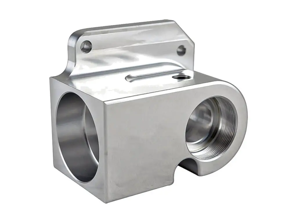
CNC machined 6061-T6 aluminium clevis blocks with two parallel bores held to H7, bore-to-bore parallelism 0.02 mm and a flat.
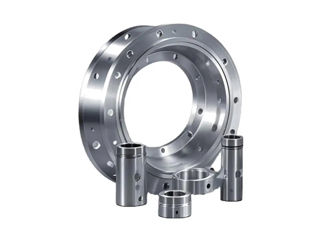
CNC turned 6061-T6 aluminium bearing ring flanges with a bored bearing seat to H7, bolt circle to ±0.03 mm, faces flat to 0.02 mm.
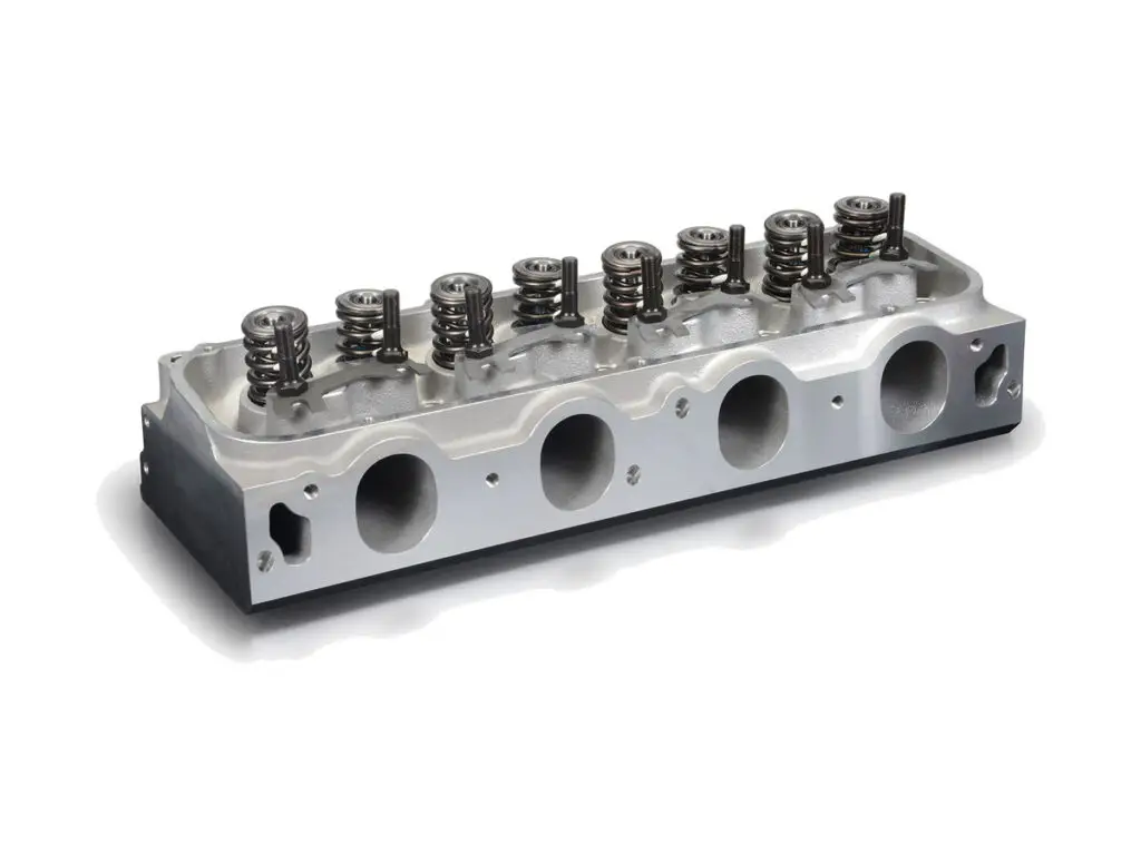
Five-axis machined billet aluminium cylinder heads with combustion chambers, valve seats and cam bores held to 0.015 mm, deck.
CNC turned aluminium stepped spacer bushings with parallel faces to 0.02 mm, stepped shoulder square to the bore and teal or.
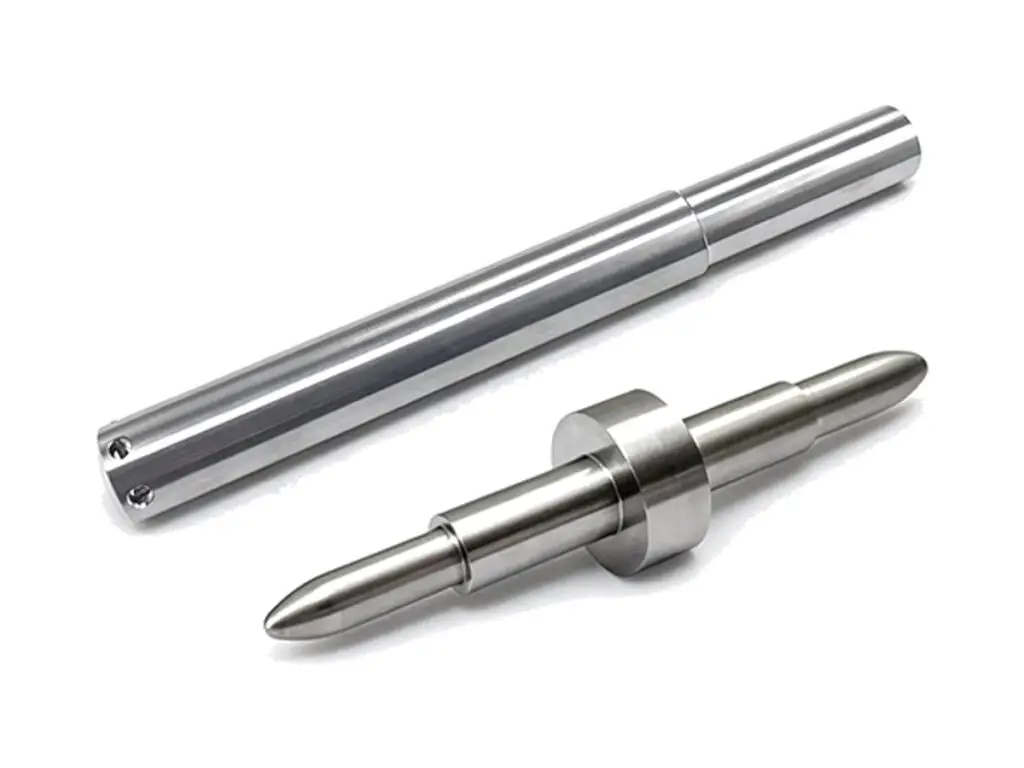
CNC turned aluminium guide shafts and positioning pins with stepped diameters ground to h6, straightness 0.02 mm per 100 mm and.
Get high‑quality machined parts in as fast as 4 days with our expanded automated CNC milling!