
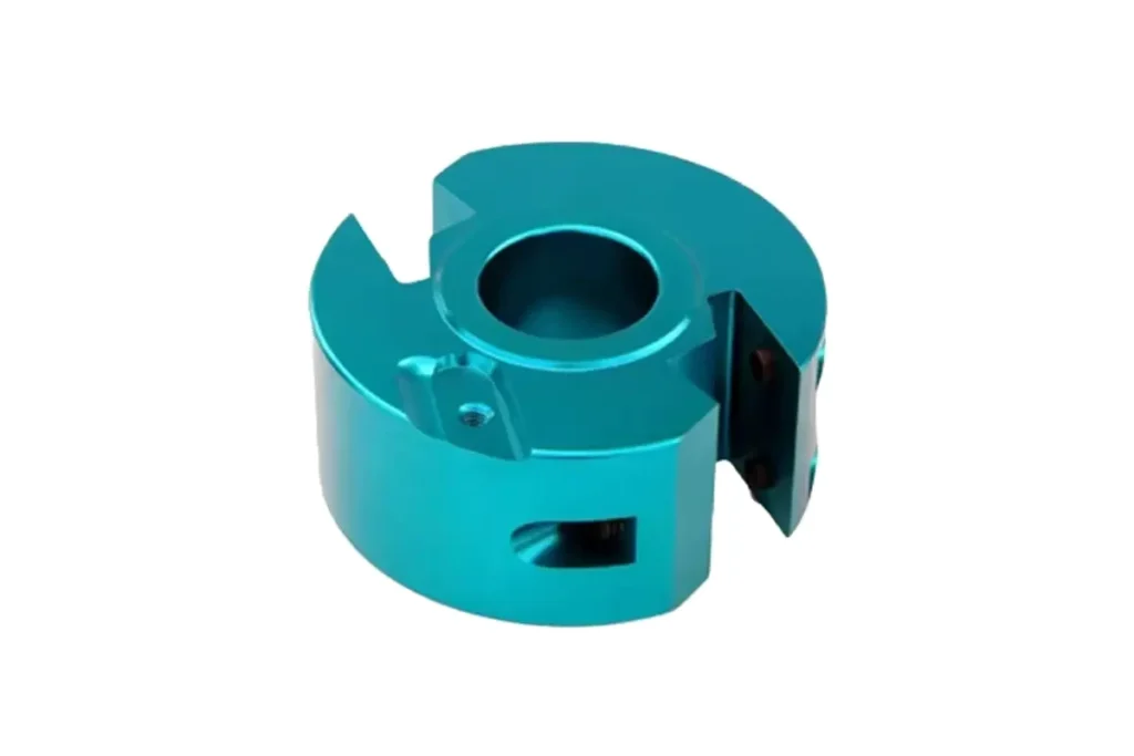
Shock Mount CNC Milled
Built for suspension systems that require secure fit and precise alignment, our CNC Machined Aluminum Shock Mount combines accurately machined mounting holes, bearing or bushing seats, and clevis features to support stable installation and dependable load transfer.
- Precision CNC Milling
- Accurate Mounting Alignment
- 6061/7075 Aluminum Options
- Prototype to Production
*Our engineering team helps review machining requirements and provide suitable production solutions.
Shock Mount CNC Milled Overview
Precision CNC Milled Shock Mount components engineered for accurate alignment, controlled bearing or bushing fit, and stable support at the shock absorber mounting point.
A Shock Absorber Mount creates the structural connection between the damper and the suspension or chassis. Its design must hold the correct mounting position while integrating functional features such as bores, clevis sections, mounting holes, and reinforced load areas.
For a CNC Milled Shock Mount, accuracy depends on more than individual dimensions. The relationship between the mounting holes, bearing or bushing seat, clevis width, and mating faces must remain consistent throughout machining. Precision CNC milling also allows pockets, angled surfaces, and reinforced sections to be produced within the same component while maintaining the required assembly geometry.
At SinoRise, every Aluminum Shock Mount is manufactured around the customer’s drawing rather than a fixed standard design. Machining strategies can be adjusted for different aluminum grades, bore sizes, mounting layouts, clevis structures, finishes, and inspection requirements, supporting design validation, low-volume builds, and repeat production.


6061 Aluminum
6061 aluminum is a practical material for a cnc machined aluminum shock mount, offering a good balance of machinability, corrosion resistance, structural strength, and low weight.
It works well for automotive suspension components, motorcycle assemblies, and custom mechanical applications where lightweight construction and efficient CNC machining are important.

7075 Aluminum
7075 aluminum is well suited to a cnc machined shock mount where higher strength and structural rigidity are required without adding unnecessary weight.
It is commonly used for performance vehicles, racing suspension systems, off-road applications, and other projects where the component is subjected to greater mechanical loads.
Not Sure Which Aluminum Grade Fits Your Shock Mount? Send us your drawing and application requirements for material and machining recommendations.
CNC Machined Shock Mount Specifications
Key machining data for aluminum shock mount components, covering mounting geometry, bore fit, tolerances, structural features, finishes, inspection, and custom production requirements.
| Specification | Machining Data | Specification | Machining Data |
|---|---|---|---|
| Product Type | CNC Milled Aluminum Shock Mount | Bore Machining | Drilling, Reaming, Boring |
| Material | 6061 Aluminum, 7075 Aluminum | Mounting Features | Mounting Holes, Clevis, Bearing / Bushing Seats |
| Machining Process | CNC Milling, 3-Axis / 4-Axis / 5-Axis Machining | Thread Options | Metric / Imperial Threads |
| Typical Tolerance | \u00b10.01\u2013\u00b10.05 mm, based on feature and drawing requirements | Critical Control | Bore Size, Hole Position, Clevis Width, Mounting Alignment |
| Surface Roughness | Ra 0.8\u20133.2 \u03bcm, depending on functional surface requirements | Surface Finish | Anodizing, Hard Anodizing, Bead Blasting, As Machined |
| Machined Features | Clevis Features, Pockets, Ribs, Angled Surfaces, Multi-directional Holes | Inspection | Bore Diameter, Hole Position, Mating Surface, Dimensional Inspection |
| Structural Design | Lightweight Pockets, Reinforced Load Areas, Multi-face Geometry | Inspection Equipment | 2.5D Measuring System, Digital Height Gauge, CMM |
| Production Type | Prototype, Low-volume, Small & Medium Batch Production | Drawing Format | STEP, STP, IGES, DWG, DXF, PDF |
| Customization | Bore Size, Hole Layout, Clevis Geometry, Material, Finish, Tolerance | Manufacturing Basis | Customer Drawings, 3D CAD Models, Technical Specifications |
Key Features of Our Shock Absorber Mounts
Built to support stable suspension connection, consistent assembly, and the structural demands of custom suspension bracket applications.
Stable Load Transfer
A shock absorber mount forms a key load path between the damper and the suspension or chassis structure.A rigid aluminum body helps distribute forces through the mounting area while maintaining structural stability during repeated suspension movement.
Consistent Assembly Fit
Consistent part geometry helps reduce variation during installation and makes replacement or repeated assembly more predictable.This is particularly important for suspension systems where component position can influence shock orientation, clearance, and overall assembly behavior.
Suspension Durability
An aluminum shock mount may operate under vibration, repeated loading, moisture, road debris, and changing environmental conditions.Suitable material selection and surface treatment help balance low weight, corrosion resistance, and durability for automotive and mechanical applications.
Custom Fit for Different Designs
Different vehicle platforms and suspension layouts often require different mounting geometry.SinoRise can adapt a suspension bracket or related mounting component to project-specific installation space, shock absorber configuration, connection method, and functional requirements.
Need a Shock Mount Built for Your Suspension Design?
Surface Finishes for Aluminum Shock Mounts
Finishing options for cnc machined shock mount components are selected according to wear exposure, corrosion risk, operating environment, and appearance requirements.
| Finish | Main Purpose | Finish | Main Purpose |
|---|---|---|---|
| Anodizing | Improve corrosion resistance and provide a durable protective surface for aluminum shock mounts | Hard Anodizing | Increase surface hardness and wear resistance for more demanding suspension applications |
| Bead Blasting | Create a uniform matte finish and reduce visible machining marks | Powder Coating | Add protective coverage and improve resistance to environmental exposure |
| Polishing | Produce a smoother surface and improve visual appearance | As Machined | Retain the original CNC-machined finish where additional coating is not required |
*Surface finish selection should be based on material grade, operating environment, wear exposure, appearance requirements, and drawing specifications.

Put your CNC milling parts into production today
All information and uploads are secure and confidential.
Trusted for Precision CNC Machined Components
Supporting OEM projects with accurate machining, flexible production, and reliable component quality.





Trusted for Precision CNC Milling.
CNC Production Process for Shock Absorber Mounts
From geometry review and material preparation to final inspection, each aluminum shock mount follows a controlled production sequence focused on fit, dimensional consistency, and suspension assembly requirements.
01. Suspension Geometry Review
Review the drawing, CAD model, mounting direction, bore dimensions, clevis geometry, and critical assembly relationships before machining begins.For a shock absorber mount, this step helps define the correct machining datums and identify the areas most important to suspension fit and load transfer.
02. Aluminum Blank Preparation
Prepare 6061 or 7075 aluminum stock according to the finished dimensions, clamping strategy, and machining allowance.The selected material and blank condition are checked before production to ensure a stable starting point for the aluminum shock mount.
03. Multi-Feature CNC Milling
Machine the main profile, clevis sections, weight-reduction pockets, ribs, angled faces, and multi-directional mounting features.For a cnc milled shock mount, the machining sequence is arranged to maintain stable reference surfaces and reduce unnecessary repositioning between operations.
04. Bore, Hole & Finish Processing
Complete bearing or bushing bores, mounting holes, threads, and critical mating areas, then remove burrs and prepare the part for the specified finish.Surface treatments such as anodizing, hard anodizing, or bead blasting can be applied according to the final operating environment and drawing requirements.
05. Fit & Dimensional Inspection
Check bore diameter, mounting hole position, clevis width, mating surfaces, and other drawing-defined dimensions.Final inspection confirms that the cnc machined shock mount maintains the required fit and positional relationship for the suspension assembly.
Ready to Start Your Shock Mount Project? Send us your drawing and key requirements for machining evaluation.
FAQs About CNC Machined Shock Mounts
6061 aluminum is a practical choice for many automotive and motorcycle suspension applications because it offers good machinability, corrosion resistance, and balanced strength. For a cnc machined aluminum shock mount that requires higher strength and rigidity while remaining lightweight, 7075 aluminum may be more suitable.
Key dimensions usually include the bearing or bushing bore, mounting hole position, clevis width, mating faces, and the positional relationship between these features. Accurate control of these areas helps maintain proper fit, alignment, and installation stability within the suspension assembly.
Yes. Depending on the geometry, a cnc milled shock mount can include clevis sections, angled faces, pockets, ribs, and multi-directional holes. 3-axis, 4-axis, or 5-axis machining can be selected according to feature access and part complexity.
Anodizing is commonly selected for corrosion protection and appearance, while hard anodizing can provide greater surface hardness and wear resistance. Bead blasting, powder coating, or an as-machined finish may also be used depending on operating conditions and drawing requirements.
Repeat production relies on stable machining datums, controlled process sequences, and inspection of critical features. For a suspension bracket or related mounting component, bore size, hole position, clevis width, mating surfaces, and overall dimensional relationships are typically checked throughout production.
For a more accurate machining review, provide a 2D drawing or 3D CAD model together with the required material, quantity, surface finish, critical tolerances, and inspection requirements. This allows SinoRise to evaluate machining feasibility and define a suitable production approach.
Other CNC Machined Mechanical Components
Explore additional precision CNC machined components manufactured for OEM applications and customized production needs.

Lightweight CNC-machined frames designed for stable component integration, accurate arm positioning, and reliable UAV assembly.

Precision-machined chamber structures developed for controlled sealing, accurate port positioning, and reliable vacuum system integration.

Precision-machined clutch levers shaped around smooth pivot action, comfortable reach, and consistent motorcycle control.

Precision-machined bearing housing components designed for accurate assembly, stable operation, and customized mechanical applications.

Structural aluminum engine brackets CNC machined for accurate mounting and long-term stability.
Get high‑quality machined parts in as fast as 4 days with our expanded automated CNC milling!