
Holes and internal threads often determine whether a machined part locates correctly, holds a bearing, seals, or assembles without damage. A drilled clearance hole, a reamed dowel hole and a tapped mounting hole may look similar in CAD, but they require different machining and inspection methods.
The correct process starts with function. Drilling creates the initial hole. Boring can improve its path and geometry. Reaming finishes a near-size hole to a controlled diameter. Tapping or thread milling creates an internal thread. Inspection must then verify what matters: size, position, fit, usable thread depth or thread class.
This guide explains how to select the right CNC hole machining process, avoid common design errors and define inspection requirements for prototype and production parts.
CNC Holes and Threads at a Glance
| Process | Main purpose | Typical use | Common inspection |
| Drilling | Creates the initial hole | Clearance and pilot holes | Pin gauge, plug gauge or depth check |
| Boring or interpolation | Enlarges and corrects an existing hole | Bearing and precision bores | Bore measurement and CMM where required |
| Reaming | Finishes a near-size hole | Dowel holes and controlled fits | Plug gauge, bore measurement and position check |
| Cutting tap | Cuts internal threads | Standard threaded holes | GO/NO-GO thread plug gauge |
| Form tap | Forms threads without chips | Ductile materials | GO/NO-GO thread plug gauge |
| Thread milling | Cuts threads by helical interpolation | Large, custom or high-risk threads | Thread gauge, depth and position inspection |
The final route depends on diameter, depth, material, wall thickness, tolerance, quantity and tool access.
Start With the Function of the Hole
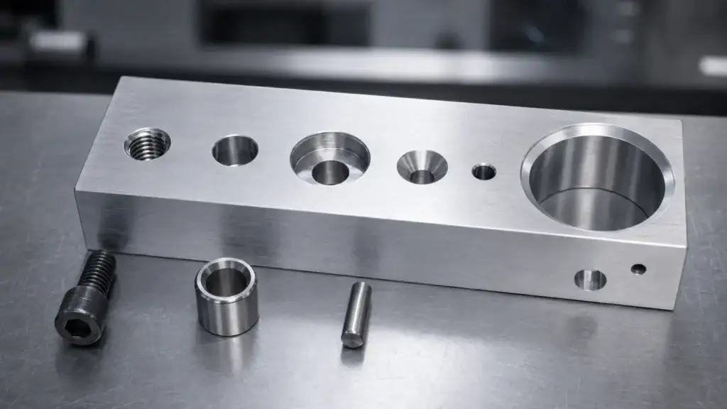
A hole should not be specified only by nominal diameter.
A clearance hole allows a bolt or pin to pass through and normally does not locate the assembly. Standard drilling is often sufficient when diameter, burr condition and position provide enough clearance.
A locating hole establishes repeatable position between components. Dowel holes usually require tighter diameter and location control. A common route is to drill undersize and ream to the final fit, then inspect position relative to the datums.
Bearing and bushing bores may require controlled diameter, roundness, cylindricity and surface condition. Depending on size and geometry, they may be bored, circular-interpolated, reamed or finished by another process.
A threaded hole must provide the specified thread size, pitch, class and usable engagement depth. Blind threads also require enough space for tool lead, chips and the drill-point region.
Starting with function prevents two costly mistakes: using a precision process for a simple clearance hole, or relying on drilling alone for a feature that controls assembly location.
Drilling Creates the Initial Hole
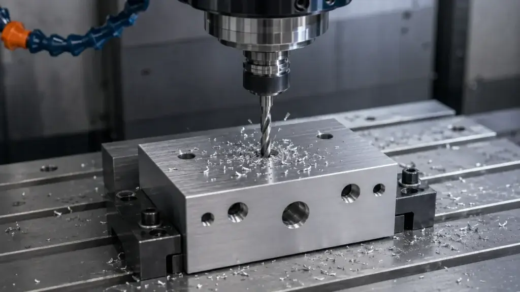
Drilling is usually the fastest CNC drilling process for producing round holes in solid material. The machine controls the coordinates, while the drill creates the initial diameter and depth.
A drill entering a flat surface is generally more stable than one entering an angled, curved or interrupted surface. Spotting or milling may be used to establish a controlled starting point. Cross-holes and uneven breakthrough can push the drill sideways, affecting direction and exit location.
Through holes allow chips to leave after breakthrough, although exit burrs still need control. Blind holes retain chips and require a defined total depth. The usable cylindrical depth is shorter than the drill travel because a conventional drill leaves a conical point.
As the depth-to-diameter ratio increases, chip evacuation, runout, heat and straightness become more difficult to control. A deep hole drilling process may require pecking, internal coolant or dedicated tooling.
Drilling alone does not automatically guarantee tight control of position, straightness, roundness, cylindricity or surface roughness. Functional holes may need a secondary operation.
When to Use Boring or Reaming?
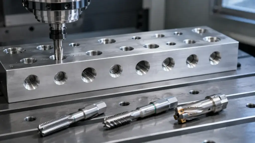
Boring and reaming work on existing holes, but they solve different problems.
Boring or circular interpolation can enlarge a hole, re-establish its center path and improve alignment with the machine coordinate system. These methods are useful when the initial drilled hole does not provide sufficient position or geometry.
Reaming removes a small, controlled allowance from a near-size hole. Its main purposes are to improve final diameter, consistency and surface condition. Typical applications include dowel holes, slip fits and selected press fits.
A reamer is guided by the existing hole. It should not be expected to correct a substantial position error or badly misaligned path.
A straightforward locating-hole process may be:
Establish position → Drill undersize → Ream to final size
Where position or direction needs more control:
Establish position → Drill → Bore or interpolate → Ream if needed
Not every precision hole requires all three operations. The part function and manufacturing risk should determine the route.
Tapping, Form Tapping or Thread Milling
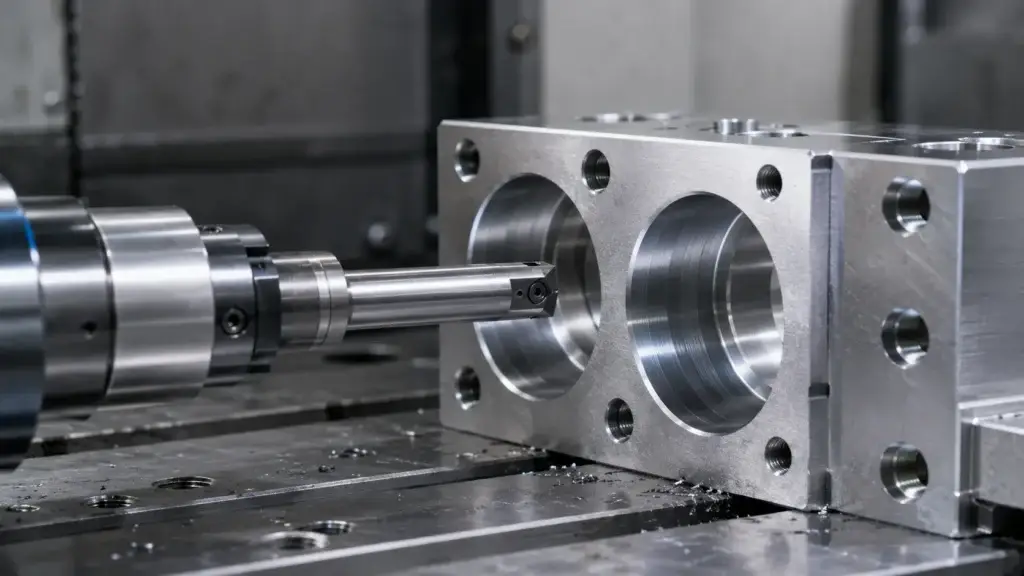
The thread cutting process starts with a correctly prepared pilot hole. Pilot diameter, material, entrance condition and available depth strongly affect thread quality.
Cutting Taps
A cutting tap removes material to form the thread. It is efficient for many standard sizes but produces chips. In a blind hole, chips can pack at the bottom, raise torque and break the tap.
The tap style should match the hole type and material. A tool designed to push chips forward through a through hole may not be suitable for a closed blind feature.
Form Taps
A form tap displaces ductile material instead of cutting it. It produces no chips and can create a strong thread in suitable materials.
Form tapping requires:
- A forming-specific pilot diameter
- A material capable of plastic deformation
- Suitable lubrication
- Adequate machine torque
- Enough material around the hole
It is not suitable for every alloy, brittle material or thin-wall component.
Thread Milling
A thread mill follows a helical path inside the hole. It is useful for:
- Large internal threads
- Custom thread forms
- Difficult materials
- High-value parts
- Left-hand and right-hand threads
- Applications requiring pitch-diameter adjustment
Thread milling creates smaller chips and is generally easier to recover from if the tool fails. For many standard small threads and higher quantities, rigid tapping remains faster.
The correct choice depends on thread size, depth, material, quantity, machine capability and the cost of tool failure.
Blind Holes and Usable Thread Depth
A blind tapped hole contains several zones:
- Full usable thread
- Incomplete threads from the tap lead
- Tap-travel clearance
- Chip space where applicable
- The conical drill-point region
Therefore:
Usable thread depth < Tap travel depth < Total drilled depth
The exact allowances depend on thread size, tap design, drill geometry and material.
The drawing should specify the required full thread depth. When bottom clearance is limited, it should also define the total hole depth or minimum remaining wall thickness.
Do not design the screw to bottom out in the hole. Clamping should normally result from contact between the assembled surfaces, not from the screw tip reaching the drill point.
Hole Size, Position and GD&T
Diameter and position answer different questions.
Diameter controls how large the hole is and influences clearance, slip fit, press fit or thread preparation.
True position controls where the hole axis lies relative to defined datums.
A hole can meet its diameter tolerance and still prevent assembly if its center is misplaced. Depending on function, a drawing may also control:
- Perpendicularity
- Straightness
- Roundness
- Cylindricity
- Coaxial relationships
- Hole-pattern position
These requirements should be applied selectively.
A clearance-hole pattern may need realistic position control but not an extremely tight diameter. A bearing bore may require both diameter and geometric control. A dowel pattern often needs controlled fit and datum-based position.
How to Inspect CNC Holes and Threads?
Inspection should match the feature’s function.
| Feature | Main inspection requirement | Common method |
| Clearance hole | Diameter and burrs | Pin or plain plug gauge |
| Reamed dowel hole | Fit diameter and position | Plug or bore measurement plus CMM position |
| Bearing bore | Diameter and geometry | Bore measurement, CMM or dedicated gauge |
| Hole pattern | Position relative to datums | CMM, optical system or functional gauge |
| Blind hole | Cylindrical and total depth | Depth measurement or suitable probe |
| Tapped hole | Thread class and usable depth | GO/NO-GO thread plug gauge and depth check |
| Countersink | Diameter, angle and seating | Optical, dimensional or dedicated inspection |
Pin and plug gauges provide quick functional size checks, but they do not prove hole position.
Bore measurement can evaluate actual diameter at selected depths and orientations. CMM and optical systems are useful for hole patterns and datum-based geometric relationships.
Internal threads are commonly verified with the applicable GO/NO-GO thread plug gauge. A separate coordinate inspection may still be required when threaded-hole position is critical.
Trial assembly with a screw can confirm basic fit, but it is not a complete substitute for thread-gauge inspection.
Common Hole and Thread Failures
| Problem | Likely cause | Corrective focus |
| Oversized hole | Runout, wear or unstable entry | Tool condition and process stability |
| Tapered hole | Deflection, heat or thin-wall movement | Support, tool reach and finishing method |
| Reamed hole off-position | Pilot path was already incorrect | Correct the path before reaming |
| Excessive exit burr | Breakthrough conditions or worn drill | Breakthrough strategy and deburring |
| Broken tap | Pilot too small, chip packing or misalignment | Pilot size, tap type and lubrication |
| Loose thread | Pilot too large or worn tool | Pilot process and pitch-diameter control |
| GO gauge fails | Undersized thread, burrs, coating or inadequate depth | Thread size, entry and finished condition |
| Pattern does not assemble | Position or datum error | Datum structure and positional inspection |
A defect should be traced through the complete process chain rather than blamed only on the final drill, reamer or tap.
How to Specify Holes and Threads on a Drawing?
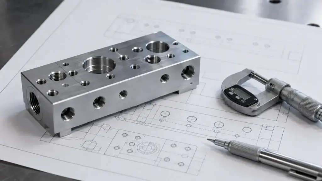
For plain holes, include:
- Diameter and tolerance
- Through or blind condition
- Cylindrical or total depth
- Fit requirement
- Position and datums where needed
- Counterbore, countersink or spotface details
- Surface roughness when functional
- Inspection or reporting requirements
For threaded holes, include:
- Thread standard
- Nominal size
- Pitch or threads per inch
- Thread class
- Full usable thread depth
- Through or blind condition
- Insert requirements
- Inspection condition before or after coating
The STEP model and 2D drawing should use the same revision. Thread geometry is often simplified in 3D models, so the drawing remains essential for complete thread definition.
What Determines Hole and Thread Machining Cost?
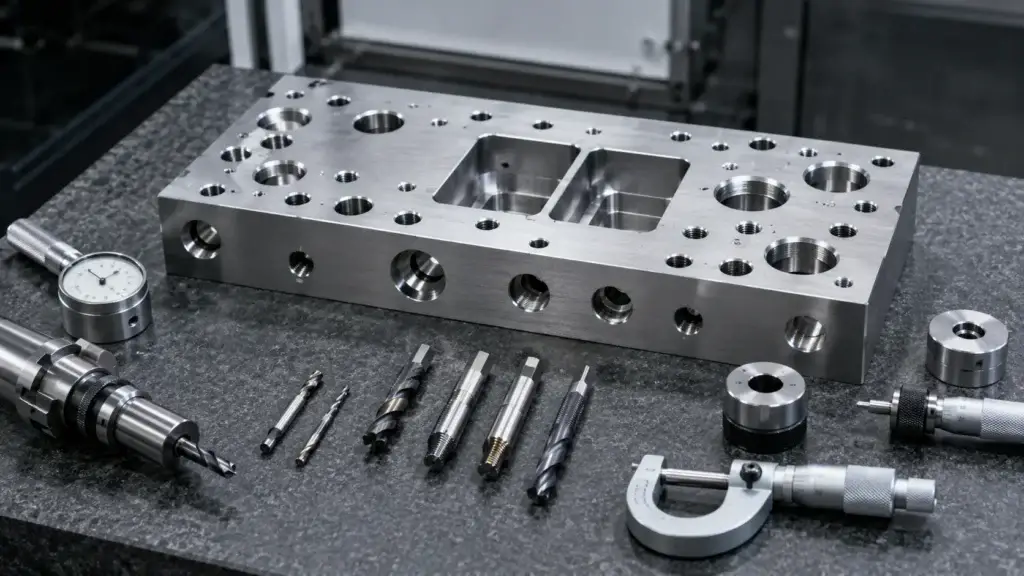
The cost of CNC milling holes and threads is influenced by:
- Hole diameter and depth
- Through or blind geometry
- Material
- Tool changes
- Deep-hole chip control
- Diameter and position tolerance
- Reaming or boring operations
- Standard or custom thread tools
- Tapping versus thread milling
- Deburring and cleaning
- Inspection reports
- Production quantity
A standard drilled clearance hole is usually economical. A blind precision bore with tight positional control, followed by threading and documented inspection, requires more programming, tooling and quality work.
Cost can often be reduced by using standard drill, reamer and thread sizes, avoiding unnecessarily deep blind holes and applying tight tolerances only to functional features.
Three Practical Examples
Semiconductor Fixture Dowel Holes
Two dowel holes locate a removable fixture component. Diameter controls the fit, while the pattern controls repeatable assembly.
The process may use controlled drilling followed by reaming. Final inspection should verify both hole size and position relative to the fixture datums.
Robotic Housing Blind Threads
An aluminum housing contains blind threads near thin outer walls.
The review should confirm pilot size, usable thread depth, bottom clearance, wall thickness and whether anodizing will affect the threads. Where the threads are not masked, inspection may need to take place after finishing.
Optical Mounting Plate
An optical plate contains both clearance and locating holes.
Clearance holes may use standard drilling, while locating holes require tighter fit and datum-based position. Separating these requirements avoids unnecessary reaming and inspection across the complete hole pattern.
How SinoRise Supports Hole and Thread Machining?
SinoRise reviews each hole according to its function, material, depth, tolerance, finishing condition and inspection requirement. A precision CNC milling plan can combine drilling, circular interpolation, reaming, tapping and thread milling rather than applying one process to every feature.
SinoRise operates more than 40 precision machining machines and uses inspection equipment including 2.5D measuring systems, digital height gauges and CMM equipment. Its ISO 9001 quality system supports projects in medical equipment, UAVs, semiconductor systems, robotics, optical instruments and automotive or motorcycle components.
For quotation, provide the STEP model, 2D drawing, material, quantity, hole and thread callouts, datums, surface treatment and required inspection reports.
Frequently Asked Questions
What is the difference between drilling and reaming?
Drilling creates the initial hole. Reaming removes a small allowance from an existing hole to improve its final diameter, consistency and surface condition.
Can reaming correct hole position?
Not reliably when the original hole is significantly misplaced. Boring or circular interpolation may be needed before reaming.
When does a dowel hole need reaming?
Reaming is commonly used when the fit needs more size control and repeatability than standard drilling provides. Position must still be controlled separately.
What is the difference between boring and reaming?
Boring can enlarge and help correct an existing hole path. Reaming mainly finishes a near-size hole to its final diameter.
Should I use tapping or thread milling?
Tapping is efficient for many standard threads. Thread milling offers more flexibility for large, custom, difficult-material or high-risk threaded features.
What is the difference between a cutting tap and a form tap?
A cutting tap removes material and creates chips. A form tap displaces ductile material without producing chips.
Why must a blind tapped hole be drilled deeper?
Extra depth is required for the tap lead, tool travel, chip space and the drill-point shape below the full usable thread.
How are reamed holes inspected?
Size may be checked with a suitable plain gauge or bore measurement. Critical position and datum relationships may require CMM or another coordinate inspection method.
How are internal threads inspected?
Internal threads are commonly checked with the specified GO/NO-GO thread plug gauge, together with usable-depth verification where required.
Can a CMM replace a thread plug gauge?
A CMM is useful for position and geometric relationships. A thread plug gauge is generally the more direct functional check for an internal thread class.
Request a Hole and Thread DFM Review
Send SinoRise your 3D model, 2D drawing, material, quantities, hole fits, thread specifications, surface treatment and inspection requirements.
The engineering team will review feature functions, machining sequence, blind-hole depth, tolerance risks and inspection needs before quotation.