
A CNC-milled surface is rarely perfectly smooth. The cutter leaves a directional pattern shaped by tool geometry, feed, stepover, machine rigidity and material behavior. These marks may be completely acceptable on a hidden structural surface but unsuitable for a seal, sliding interface, optical mount or visible enclosure.
Surface quality should therefore be specified according to function rather than appearance alone. A lower Ra value can reduce friction or improve sealing, but it also requires more controlled machining, inspection and sometimes secondary finishing. Bead blasting can make a surface look more uniform without making it smoother, while anodizing can improve corrosion resistance but will not reliably hide deep tool marks.
This guide explains common CNC milling Ra values, the causes of machining marks, available CNC finishing options, inspection methods and the effect of surface requirements on total manufacturing cost.
CNC Milling Surface Finish at a Glance
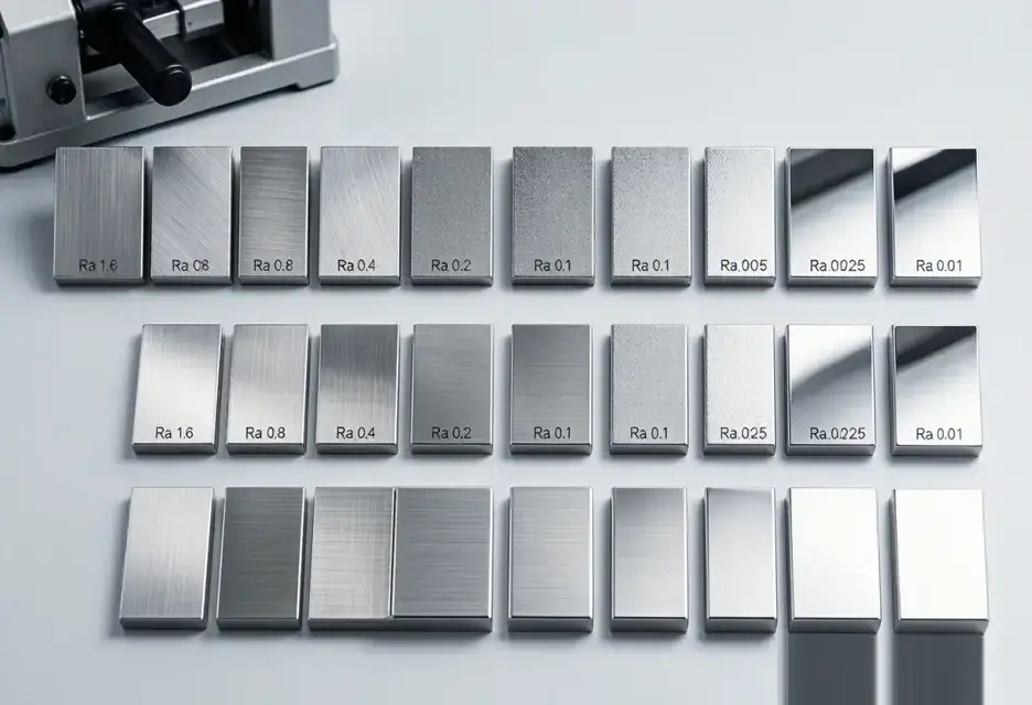
These values are general planning references. Actual capability depends on material, geometry, tool access, surface direction, machine condition and inspection method.
Surface Finish, Surface Roughness and Surface Finishing
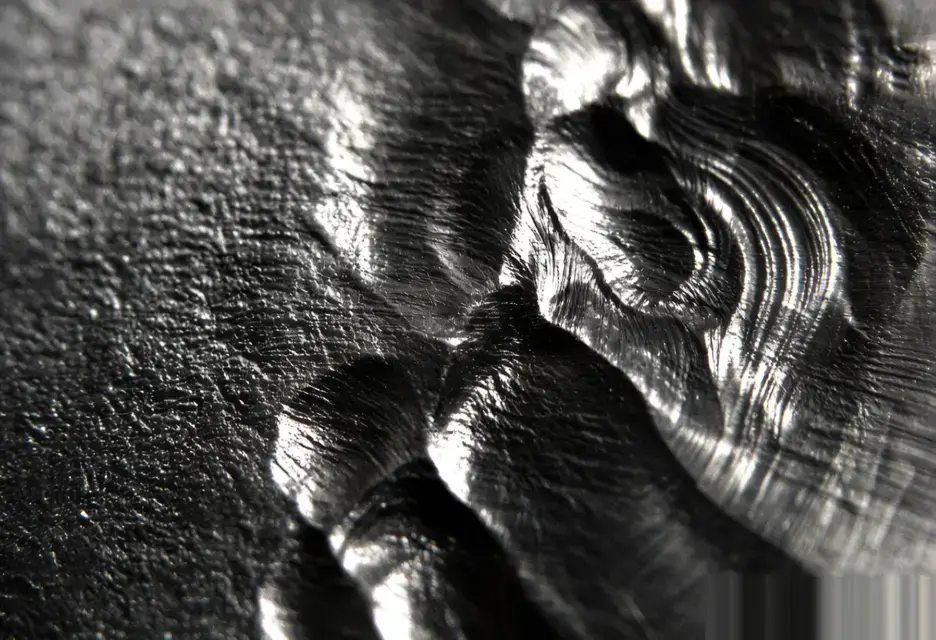
These terms are related but do not mean the same thing.
Surface finish
Surface finish describes the overall condition of a manufactured surface. It can include:
- Roughness
- Waviness
- Tool-path direction
- Scratches
- Chatter marks
- Burrs
- Reflectivity
- Coating texture
- Cosmetic appearance
Surface roughness
Surface roughness describes the small, closely spaced peaks and valleys left by the manufacturing process. It is commonly measured with Ra or Rz.
The keyword surface finish and roughness is often used as though both terms are interchangeable, but roughness is only one part of the complete surface condition.
Surface finishing
Surface finishing is the process used to alter the machined surface after or during CNC machining.
Examples include:
- Fine machining
- Bead blasting
- Brushing
- Polishing
- Anodizing
- Passivation
- Electropolishing
- Powder coating
A finishing process may improve appearance, corrosion resistance or wear performance without necessarily reducing measured roughness.
What Do Ra and Rz Mean?
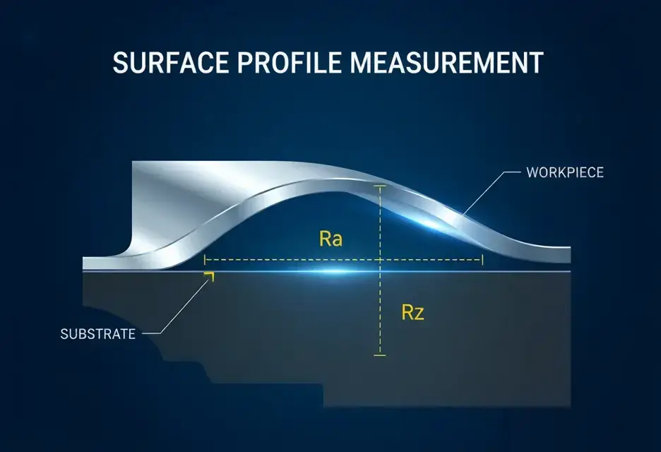
Ra: average surface roughness
Ra is the arithmetic average of the surface-profile deviations from a center line over a specified sampling length.
It is the most common roughness parameter because it provides a simple number for comparing surfaces.
However, Ra does not describe the complete profile. A surface with one deep scratch may produce a similar Ra result to a surface with many smaller, evenly distributed marks.
Rz: average peak-to-valley height
Rz represents the vertical distance between prominent peaks and valleys across measured sections.
It is more sensitive to isolated surface defects than Ra and may be useful for:
- Sealing surfaces
- Sliding interfaces
- Fatigue-sensitive parts
- Surfaces where deep scratches are unacceptable
Why identical Ra values may look different
Two parts with the same Ra may still appear or perform differently because of:
- Different tool-path directions
- Different spacing between cutter marks
- Chatter on one surface
- Isolated scratches
- Different waviness
- Different materials and reflectivity
- Different blasting or polishing processes
For critical surfaces, Ra may need to be combined with Rz, lay direction, dimensional tolerance or a cosmetic standard.
Common Ra Values for CNC Milling
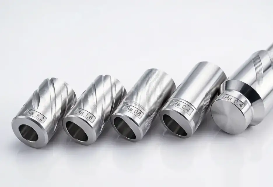
Ra 3.2 µm: standard as-machined finish
Ra 3.2 µm is a common reference for a standard as-machined surface finish.
The surface may feel smooth to the touch but still show visible milling paths. It is often suitable for:
- Internal housing surfaces
- General brackets
- Fixture components
- Clearance pockets
- Non-contact structural faces
A standard finish is usually the most economical option because it does not require a separate low-feed finishing process.
Ra 1.6 µm: fine-machined surface
Ra 1.6 µm typically requires a dedicated finishing pass with controlled tooling and cutting parameters.
It may be suitable for:
- Mounting faces
- General mating surfaces
- Precision equipment components
- Selected bearing support surfaces
- Parts where visible cutter marks should be reduced
The requirement should be applied only to the surfaces that need it. Specifying Ra 1.6 across every face can add machining time without improving product function.
Ra 0.8 µm: precision functional surface
Ra 0.8 µm is a more demanding CNC surface roughness requirement.
Achieving it consistently may require:
- A rigid setup
- Short tool overhang
- Low tool runout
- A sharp finishing cutter
- Smaller stepover
- Stable cutting engagement
- Dedicated inspection
It may be used on sliding surfaces, precision locating faces and certain sealing interfaces. Feasibility still depends on material and geometry.
Ra 0.4 µm and below
Ra 0.4 µm may be possible by controlled precision milling on suitable rigid and accessible surfaces. It should not be treated as a universal CNC milling capability.
Deep cavities, thin walls, complex curves and difficult materials may require:
- Grinding
- Lapping
- Honing
- Diamond machining
- Mechanical polishing
- Electropolishing
The engineering team should determine whether the required Ra must come directly from milling or may be produced by a secondary process.
Why CNC-Milled Parts Have Tool Marks?

Not all CNC milling tool marks indicate a defect. Regular, shallow cutter paths are a natural result of material removal.
The important distinction is between expected machining texture and marks caused by an unstable process.
Feed marks
Feed marks are regularly spaced lines created as the cutting edge moves through the material.
Their spacing and depth are influenced by:
- Feed per tooth
- Tool diameter
- Number of cutting edges
- Tool geometry
- Cutting direction
Uniform feed marks may be acceptable when they remain within the specified Ra and cosmetic requirements.
Stepover and scallop marks
When milling a flat or curved surface with overlapping toolpaths, material remains between adjacent passes as small scallops.
Large stepover increases scallop height and makes the toolpath more visible. This is especially important when using ball-nose cutters on 3D surfaces.
Chatter marks
Chatter creates repeated waves or irregular patterns caused by vibration between the tool, spindle, workpiece and fixture.
Common causes include:
- Excessive tool overhang
- Insufficient workholding rigidity
- Unstable spindle speed
- Excessive cutting engagement
- Thin or flexible walls
- Worn cutting tools
Chatter may affect both surface quality and dimensional accuracy.
Tool deflection
Cutting force can push a long or small-diameter cutter away from the intended path.
This may create:
- Uneven sidewalls
- Taper
- Witness lines
- Different textures at different depths
- Surface variation near corners
Built-up edge
Soft or adhesive materials can accumulate on the cutting edge. The attached material changes the effective tool geometry and may tear or smear the part surface.
Built-up edge is influenced by tool sharpness, cutting speed, coating, lubrication and chip evacuation.
Chip recutting
Chips trapped between the cutter and the finished surface can create random scratches.
This is common in deep pockets, narrow cavities and materials producing high chip volumes. Coolant, air blast and toolpath planning are important for preventing chip recutting.
Witness marks
Witness marks appear where:
- Two toolpaths overlap
- Different cutters meet
- The part is repositioned
- A tool enters or exits a surface
- Multiple setups machine the same face
They may not significantly change Ra but can remain visually noticeable.
How to Improve the As-Machined Surface?
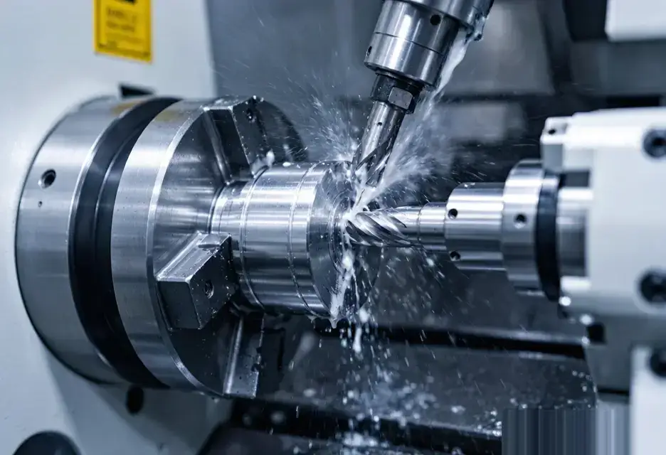
Use the right cutting tool
Tool choice should match the surface and material.
- Face mills are effective for large flat surfaces.
- Flat end mills are suitable for floors and sidewalls.
- Ball-nose cutters are used for curved surfaces.
- Sharp, polished tools help control built-up edge in aluminum.
- Wear-resistant tools are important for stainless steel and titanium.
Keep tool overhang short
Reducing cutter overhang improves rigidity and limits vibration.
The shortest tool capable of reaching the feature should normally be used. Extended tools should be reserved for areas that cannot be reached with standard tooling.
Separate roughing and finishing
Roughing removes material efficiently but leaves uneven stock and higher cutting loads.
A separate finishing pass should cut a consistent allowance with a stable tool. This improves both dimensional repeatability and surface texture.
Control feed and stepover
Lower finishing feed and smaller stepover can reduce cutter marks, but simply slowing the machine does not guarantee a better surface.
Parameters must also prevent rubbing, built-up edge and unstable cutting.
Maintain stable engagement
Sudden changes in cutter engagement can leave visible marks, particularly in corners.
Smooth lead-in and lead-out paths, constant-engagement strategies and suitable corner radii help produce a more uniform finish.
Improve chip evacuation
Coolant, air blast and open toolpaths should remove chips before they contact finished surfaces.
Chip control is especially important for deep pockets and aluminum components, where chips may accumulate quickly.
Control tool condition and runout
A chipped insert, worn cutter or excessive runout can cause one cutting edge to remove more material than the others.
Tool-life control and spindle or holder inspection are therefore part of maintaining a stable precision CNC milling surface.
CNC Milling Surface Finishing Options
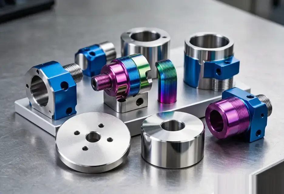
Bead blasting and sandblast finish
A sandblast finish or bead-blasted finish produces a more uniform matte appearance by striking the surface with abrasive media.
It can reduce the visibility of milling paths, but the resulting surface may have a higher measured Ra than the original machined face.
Blasting should be considered an appearance and texture process—not automatically a roughness-reduction method.
Metal polishing
A metal polish can remove fine cutter marks and increase reflectivity.
However, polishing is partly a material-removal process. Excessive polishing may:
- Round sharp edges
- Change flatness
- Alter hole entrances
- Reduce engraving depth
- Create inconsistent reflections
Functional dimensions should be protected or inspected after polishing.
Anodizing and other surface treatment
Anodizing improves aluminum corrosion resistance and can provide decorative color or greater wear resistance.
It follows the underlying surface. Deep chatter marks, scratches or witness lines may remain visible after anodizing.
For high-quality anodized parts, the usual route is:
Controlled machining → Cosmetic inspection → Bead blasting if required → Anodizing → Final inspection
How Finishing Changes Appearance, Ra and Dimensions?
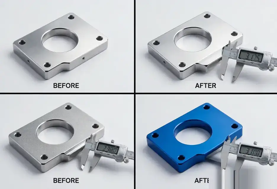
A smoother-looking surface does not always have a lower Ra.
For example:
- Bead blasting may make toolpaths less visible while increasing roughness.
- Anodizing changes color and reflectivity but retains the underlying texture.
- Polishing may reduce Ra but also remove material.
- Powder coating can hide small visual marks but adds a relatively thick layer.
- Electropolishing can reduce microscopic peaks but may affect sharp edges.
The finishing decision should therefore consider four separate outcomes:
- Functional roughness
- Cosmetic appearance
- Corrosion or wear protection
- Dimensional change
No single surface treatment optimizes all four.
How to Specify Surface Finish on a Drawing?
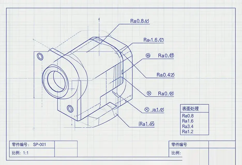
A useful drawing should identify both the requirement and the surface to which it applies.
Include:
- Required Ra value
- Rz when functionally necessary
- Specific controlled surfaces
- Lay direction where relevant
- Surface treatment type
- Coating thickness where required
- Masking areas
- Dimensions applying before or after finishing
- Inspection method or sampling requirement
- Cosmetic acceptance criteria
Avoid applying one low Ra requirement to the entire part unless every surface performs the same function.
Do not rely on “no tool marks”
A note such as “no tool marks” is difficult to manufacture and inspect because all milled surfaces contain some form of tool-path texture.
A more usable requirement may define:
- Maximum Ra
- Whether witness lines are allowed
- Acceptable scratch depth
- Required texture direction
- Cosmetic surface class
- Viewing distance and lighting
- Approved limit sample
This converts a subjective expectation into a repeatable acceptance standard.
How Surface Finish Affects CNC Milling Cost?
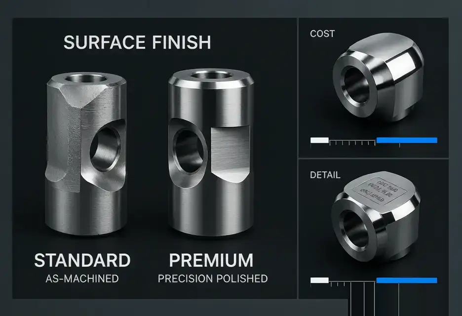
Lower roughness and stricter appearance requirements increase cost through several mechanisms.
Additional machining time
A fine surface may require:
- Separate finishing tools
- Smaller stepovers
- Lower finishing feeds
- Multiple passes
- Controlled tool entry and exit
- More frequent tool replacement
Secondary finishing
Blasting, polishing, anodizing, electropolishing and coating introduce additional handling, transport, masking and inspection.
Inspection
A specified Ra may require profilometer measurement at controlled locations and directions.
Large or critical surfaces may need several measurement points rather than one reading.
Rework and rejection risk
Cosmetic surfaces can be rejected for scratches, dents, uneven blasting, color variation or witness marks even when dimensions remain within tolerance.
The most effective way to control cost is to separate:
- Critical functional surfaces
- Visible cosmetic surfaces
- General machined surfaces
Only the surfaces that need additional control should receive it.
Surface Finish Examples by Application
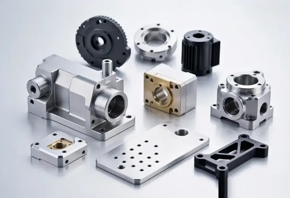
Semiconductor fixture plate
The mounting face may require controlled flatness and Ra, while internal clearance pockets can remain standard as-machined.
Bead blasting should not be applied to precision contact surfaces unless specifically required.
Robotic housing
Visible external faces may use bead blasting and anodizing for a uniform appearance. Internal mounting features can retain normal machining marks.
Cosmetic standards should define acceptable scratches, color variation and witness lines.
Medical equipment component
A stainless steel part may require a fine-machined surface followed by passivation or electropolishing.
The final requirement depends on cleaning, corrosion, contact and regulatory needs.
UAV bracket
A standard as-machined finish may be sufficient for hidden structural faces. Anodizing can provide corrosion protection, but tight holes and threads may require masking or post-finish inspection.
Optical mount
A mounting interface may require low roughness, controlled flatness and a defined non-reflective finish.
Ra alone is insufficient when reflection, lay direction or optical contact is important.
How SinoRise Supports Surface Finish Control?

SinoRise reviews surface requirements together with material, part geometry, tolerance, coating and final application. The process can separate functional surfaces from cosmetic and general machined areas so that precision is applied where it creates value.
SinoRise operates more than 40 precision machining machines and uses inspection equipment including 2.5D measuring systems, digital height gauges and CMM equipment. Its ISO 9001 quality system supports projects for medical equipment, UAVs, semiconductor systems, robotics, optical instruments and automotive or motorcycle components.
For prototype and small-batch projects, early drawing review can identify unclear Ra notes, unrealistic whole-part finish requirements, coating-related dimensional risks and surfaces that require post-treatment inspection.
Frequently Asked Questions
What is the standard Ra for CNC milling?
Ra 3.2 µm is a common reference for a standard machined surface, but the actual result depends on material, geometry, tooling and the supplier’s process.
Is Ra 3.2 considered smooth?
Ra 3.2 µm generally feels smooth but may show visible cutter paths. It is suitable for many structural and non-critical surfaces.
Can CNC milling achieve Ra 0.8 µm?
It may be achieved on suitable accessible surfaces using rigid setups, controlled tooling and dedicated finishing passes. Feature-specific review is required.
Can CNC milling achieve Ra 0.4 µm?
It may be possible in selected conditions, but grinding, lapping or polishing may be more reliable for complex geometry or repeat production.
Are tool marks normal on CNC parts?
Regular, shallow tool paths are normal. Chatter, deep witness lines, random scratches and torn material may indicate an unstable process or unacceptable appearance.
Does bead blasting reduce Ra?
Not necessarily. It can make the surface look more uniform while increasing the measured roughness.
Does anodizing hide machining marks?
Anodizing may change color and reflectivity but does not reliably hide deep marks. The underlying machined surface should be controlled before anodizing.
What is the difference between Ra and Rz?
Ra measures the average deviation of the profile. Rz is more sensitive to the distance between prominent peaks and valleys.
How should surface finish be shown on a drawing?
Identify the exact surfaces, Ra or Rz requirement, lay direction when relevant, finishing process, masking, coating condition and inspection requirements.
Request a CNC Surface Finish Review
Send SinoRise your 3D model, 2D drawing, material, required Ra values, cosmetic surfaces, surface treatment and production quantity.
Our engineering team will review machining strategy, tool-mark control, finishing compatibility, dimensional risk and inspection requirements before quotation.
Contact SinoRise for a CNC milling and surface finishing review.