
Summary
The CNC milling process is a controlled manufacturing workflow that converts a CAD design into a finished part through drawing review, manufacturability analysis, CAM programming, machine setup, material removal, finishing and inspection.
Producing accurate CNC milled parts involves more than loading a material block into a machine. Decisions made before cutting begins—including datum selection, tolerance review, tool access, workholding and machining sequence—can directly affect dimensional accuracy, surface finish, production cost and lead time.
This guide explains the complete CNC milling machine process in nine practical steps. It also identifies common manufacturing risks and shows how engineers and purchasing teams can prepare more complete project information before requesting a quote.
What Is the CNC Milling Process?
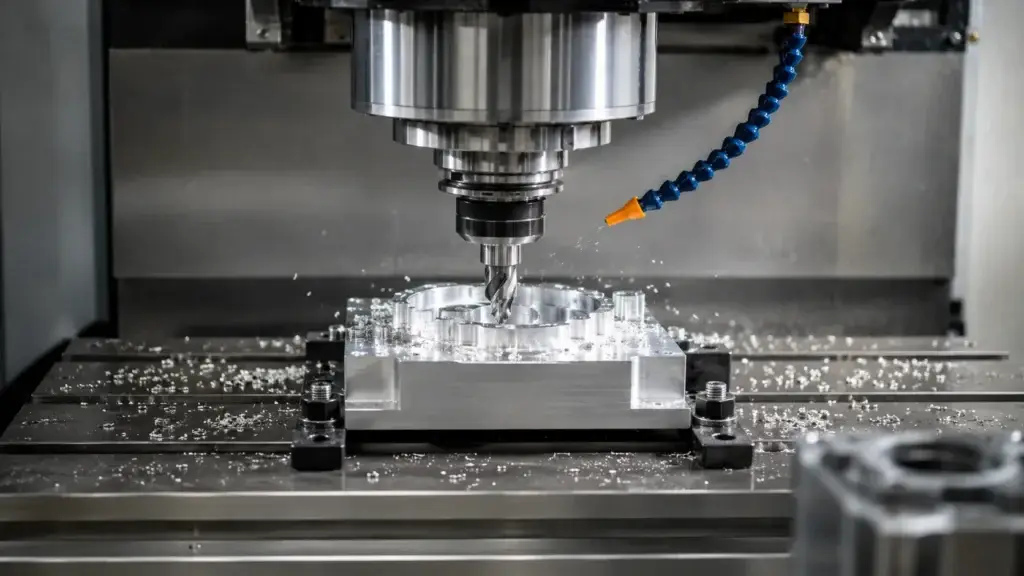
The CNC milling process is a form of subtractive manufacturing in which computer-controlled rotating cutting tools remove material from a stationary workpiece. The machine follows programmed toolpaths to create surfaces, pockets, slots, holes, threads and complex three-dimensional profiles.
A complete process extends far beyond the cutting stage. It normally includes:
- Reviewing the 2D drawing and 3D model;
- Evaluating manufacturing feasibility;
- Preparing machining datums;
- Creating CAM programs and toolpaths;
- Selecting materials, tools and fixtures;
- Setting up and calibrating the machine;
- Performing rough and finish milling;
- Deburring and surface processing;
- Inspecting the finished component.
Each stage supports the next. A correct CAM program cannot compensate for an unclear drawing, and an advanced machine cannot maintain a critical tolerance if the workpiece is poorly supported.
This is why precision CNC milling depends on the combined control of design, programming, workholding, tooling, machining parameters and inspection—not on the machine alone.
For a broader introduction to machines, materials and applications, read our guide to what CNC milling is and how it works.
How Does a CNC Milling Machine Remove Material?
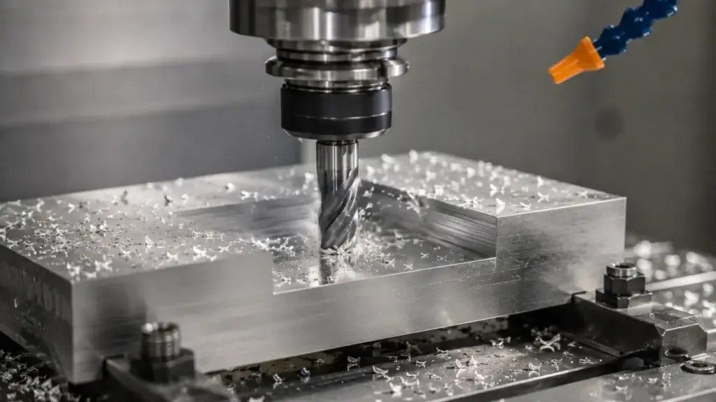
A CNC milling machine uses several coordinated systems to control material removal.
Rotating cutting tool
The spindle rotates a cutting tool at a programmed speed. Depending on the required feature, the tool may be a face mill, end mill, drill, ball nose cutter, thread mill or another specialized cutter.
The tool edges enter the workpiece and separate small amounts of material as chips. Tool geometry, coating, diameter and rigidity must be suitable for the material and feature being machined.
Workpiece and fixture
The material remains secured by a vise, soft jaws, clamps, a vacuum fixture or a custom fixture. Workholding must resist cutting forces without allowing movement or creating excessive deformation.
This balance is especially important for thin-wall components. Too little clamping force may allow the part to move, while excessive force may distort it before machining begins.
Programmed axis movement
A standard CNC mill moves along the X, Y and Z axes. Four-axis and five-axis equipment adds rotational motion, allowing the tool to reach side faces, angled features and complex surfaces more efficiently.
CNC controller and toolpath
The controller reads the machining program and coordinates:
- Tool position;
- Axis movement;
- Spindle speed;
- Feed rate;
- Depth of cut;
- Tool changes;
- Coolant operation;
- Tool and work offsets.
Together, these elements create a repeatable CNC milling machining process. However, repeatability only produces good parts when the initial program, setup and offsets are correct.
CNC Milling Process Step by Step
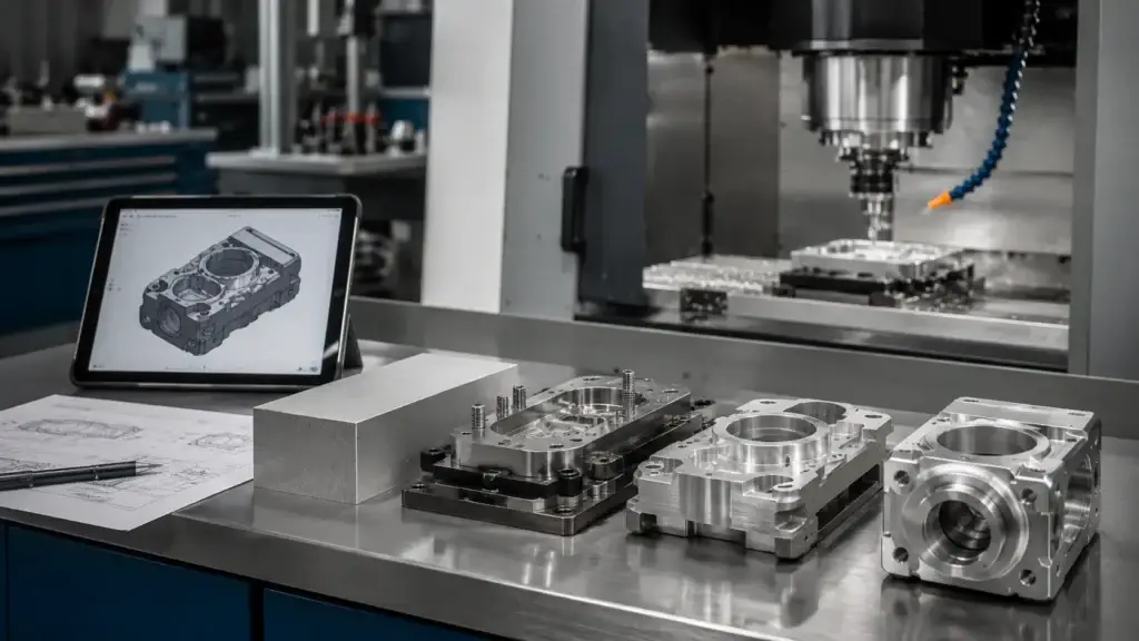
Step 1: Review the Drawing and Manufacturing Requirements
CNC milling manufacturing begins with understanding the part rather than programming the machine.
The engineering team should review:
- 2D manufacturing drawing;
- 3D CAD model;
- Material and grade;
- Critical dimensions;
- Dimensional and geometric tolerances;
- Surface roughness;
- Threads and holes;
- Surface treatment;
- Production quantity;
- Inspection documentation;
- Packaging and delivery requirements.
The 3D model defines the overall geometry, but it may not contain all the information needed for high-precision CNC milling. A 2D drawing is usually required to communicate datums, tolerances, thread specifications, surface finish and critical inspection requirements.
If the 2D drawing and 3D model conflict, the discrepancy should be resolved before production. Otherwise, the supplier may produce a dimensionally consistent part that does not meet the intended assembly requirements.
Providing complete files at the quotation stage helps reduce engineering questions, improve cost accuracy and prevent later revisions.
Step 2: Perform a DFM and Machining Feasibility Review
Design for Manufacturing analysis determines whether the proposed geometry can be produced reliably and economically.
Typical review points include:
- Whether internal corner radii allow tool access;
- Whether cavities are too deep for stable tooling;
- Whether thin walls are likely to deform;
- Whether all machined faces are accessible;
- Whether holes have practical depth-to-diameter ratios;
- Whether tolerances are tighter than the application requires;
- Whether machining and inspection datums are clearly defined;
- How many setups will be required;
- Whether the part needs 3-axis, 4-axis or 5-axis machining.
For example, a very small internal radius requires a smaller cutting tool. A smaller tool is less rigid, removes material more slowly and may have a greater risk of deflection or breakage.
Deep cavities create a similar problem. Reaching the bottom may require a long tool extension, which reduces rigidity and can produce chatter, taper or inconsistent wall finish.
Tolerance selection also matters. Applying an extremely tight tolerance to every feature can increase finishing and inspection time without improving part function. Critical tolerances should be reserved for mating surfaces, alignment features and dimensions that genuinely affect assembly or performance.
A careful DFM review is one of the most effective ways to reduce manufacturing risk before custom CNC milling begins.
Step 3: Prepare the CAD Model and Machining Datums
After the requirements are confirmed, the CAD model is prepared for machining.
The programmer identifies:
- Workpiece orientation;
- Primary and secondary datums;
- Machining coordinate system;
- Stock dimensions;
- Clamping surfaces;
- Machining allowances;
- Critical relationships between features;
- Required setup sequence.
Datum planning is particularly important for custom CNC milled parts with holes, pockets and assembly faces located on different sides.
A feature can meet its individual size tolerance but still fail inspection if its position relative to another feature is incorrect. Aligning the design datum, machining datum and inspection datum wherever practical can reduce accumulated setup error.
The programmer must also consider which material will remain available for clamping after each operation. Removing a convenient locating surface too early can make later setups less stable and more expensive.
Step 4: Create the CAM Program and Toolpaths
CAM software converts the prepared CAD geometry into a manufacturing strategy.
During programming, the engineer defines:
- Machine configuration;
- Work coordinate system;
- Cutting tools;
- Roughing and finishing sequence;
- Tool entry and exit movements;
- Spindle speeds;
- Feed rates;
- Axial and radial cutting depths;
- Stock allowance;
- Tool compensation;
- Coolant settings.
The CAM system then generates machine-readable instructions, commonly referred to as G-code.
Tool selection must account for both geometry and material. A rigid tool may remove aluminum efficiently, but stainless steel can require different tool geometry, speeds, feeds and cooling conditions. Deep pockets may require longer tools, while small internal radii require smaller diameters.
Toolpath simulation and verification
Before the program reaches the machine, the toolpath should be simulated to identify:
- Tool-to-fixture collisions;
- Tool-to-workpiece collisions;
- Excessive tool extension;
- Unmachined areas;
- Overcutting or gouging;
- Incorrect work orientation;
- Inefficient non-cutting movement;
- Unexpected remaining stock.
Simulation reduces risk, but it does not replace setup verification. The actual fixture, tool length, offsets and material position must still match the digital setup.
Step 5: Prepare the Material, Tools and Fixtures
Before production starts, the selected material must be checked against the drawing and purchasing requirements.
Material preparation can include:
- Confirming the alloy or plastic grade;
- Reviewing material certification when required;
- Cutting the blank to the appropriate size;
- Leaving sufficient clamping and machining allowance;
- Checking for visible damage or surface defects;
- Considering stress relief for sensitive components.
Different CNC milling materials behave differently during cutting.
Aluminum CNC milling can normally use higher material-removal rates because many aluminum alloys offer good machinability. Stainless steel requires more careful control of heat, tool wear and work hardening. Engineering plastics may need lower clamping forces and controlled heat generation to prevent deformation.
Fixture selection is equally important. Common options include:
- Standard machine vises;
- Machined soft jaws;
- Clamps and fixture plates;
- Vacuum fixtures;
- Dedicated production fixtures.
Prototype parts may use flexible standard workholding, while repeated production may justify a custom fixture that reduces setup time and improves consistency.
Step 6: Set Up and Calibrate the CNC Milling Machine
Machine setup converts the digital machining plan into a physical production arrangement.
The operator normally:
- Cleans the table, fixture and locating surfaces;
- Installs and aligns the workholding system;
- Loads the material in the correct orientation;
- Confirms that the workpiece contacts all locating surfaces;
- Sets the work coordinate origin;
- Loads and measures the cutting tools;
- Enters tool-length and diameter compensation;
- Checks coolant and chip evacuation;
- Runs a dry cycle or single-block verification;
- Confirms the first operation before cutting.
Minor contamination under a workpiece or fixture can change part position. An incorrect work offset can shift every machined feature. A wrong tool-length value can produce an incorrect cutting depth or a collision.
First-piece setup therefore deserves more attention than simply pressing the cycle-start button.
For thin-wall parts, clamping pressure must also be evaluated. If a component is machined while distorted by the fixture, it may appear correct during in-process measurement but change shape after it is released.
Step 7: Perform Rough Milling
Rough milling removes most of the unwanted material while leaving controlled stock for later finishing.
The primary objectives are to:
- Achieve an efficient material-removal rate;
- Maintain stable cutting forces;
- Control tool temperature;
- Remove chips effectively;
- Avoid excessive workpiece deformation;
- Leave a consistent finishing allowance.
Roughing does not aim to create the final dimension or surface finish. Trying to reach the finished size during aggressive material removal can make dimensional control less predictable.
An effective roughing strategy leaves relatively uniform stock. If some areas contain much more material than others, the finishing tool experiences changing loads. This can cause deflection, vibration and inconsistent surface quality.
For parts with substantial internal stress, roughing may also be divided into stages. The component can be allowed to relax before semi-finishing and finish machining are completed.
Step 8: Perform Semi-Finishing and Finish Milling
Semi-finishing removes the irregular stock left by roughing and establishes a consistent allowance for the final cutting pass.
It can help:
- Remove material from corners that roughing tools cannot reach;
- Correct stock distribution;
- Stabilize cutting conditions;
- Reveal deformation before final machining;
- Prepare complex surfaces for finishing.
Finish milling then creates the final dimensions, geometric relationships and surface condition.
Results at this stage are influenced by:
- Tool sharpness and wear;
- Tool and spindle runout;
- Tool extension;
- Machine stability;
- Cutting speed and feed rate;
- Direction of cut;
- Thermal expansion;
- Fixture rigidity;
- Residual material stress;
- Chip evacuation.
Reducing the feed rate does not automatically produce a better surface. If the tool rubs rather than cuts effectively, it can generate heat and produce an inconsistent finish. Cutting parameters must be matched to the tool, material, machine and required surface.
For high-precision CNC milling, temperature and inspection timing can also become important. The part, machine and measuring equipment should be allowed to stabilize when dimensional requirements are sensitive to thermal expansion.
Step 9: Deburr, Post-Process and Inspect the Part
The CNC milling machine process does not end when the spindle stops.
Deburring and cleaning
Milled parts may require:
- Manual or mechanical deburring;
- Edge breaking or chamfering;
- Removal of chips from holes and cavities;
- Cleaning of coolant and machining residue;
- Protection of sensitive surfaces.
Deburring requirements should be controlled carefully. Excessive manual work can alter critical edges or dimensions, while incomplete deburring may interfere with assembly.
Surface and secondary processing
Depending on the application, secondary processes may include:
- Anodizing;
- Passivation;
- Electroplating;
- Sandblasting;
- Polishing;
- Painting or powder coating;
- Heat treatment;
- Laser marking.
Surface treatments can alter appearance, corrosion resistance, wear resistance and, in some cases, final dimensions. Masking and coating allowances should therefore be considered before machining.
Final quality inspection
The inspection method should match the feature and tolerance being verified.
| Inspection requirement | Common measuring equipment |
| General external dimensions | Caliper or micrometer |
| Height and step dimensions | Digital height gauge |
| Hole diameter | Pin gauge, plug gauge or bore gauge |
| Thread acceptance | Thread plug or ring gauge |
| Profile and two-dimensional features | Optical measuring system |
| Position and geometric tolerances | Coordinate measuring machine |
| Surface roughness | Surface roughness tester |
SINO-V-RISE uses process checks and final inspection to verify critical dimensions, holes, threads, flatness, position and surface requirements. Its current CNC milling capabilities include 3-axis, 4-axis and 5-axis machining, supported by an ISO 9001 quality management system. View the CNC milling service capabilities.
Common CNC Milling Operations
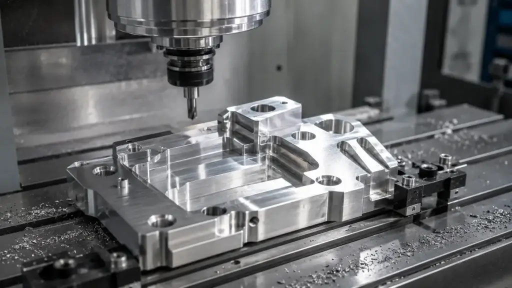
A single component often requires several operations during the complete CNC milling process.
Common operations include:
- Face milling to establish flat reference surfaces;
- End milling for pockets, profiles and general material removal;
- Shoulder milling for vertical walls and 90-degree steps;
- Slot milling for grooves, keyways and channels;
- Thread milling for internal or external threads;
- Profile milling for external boundaries;
- Contour milling for curved or freeform surfaces.
The selected operation depends on part geometry, tool access, material, tolerance and surface requirements.
For a detailed explanation of each method, see Types of CNC Milling Operations.
How 3-Axis, 4-Axis and 5-Axis Milling Change the Process?
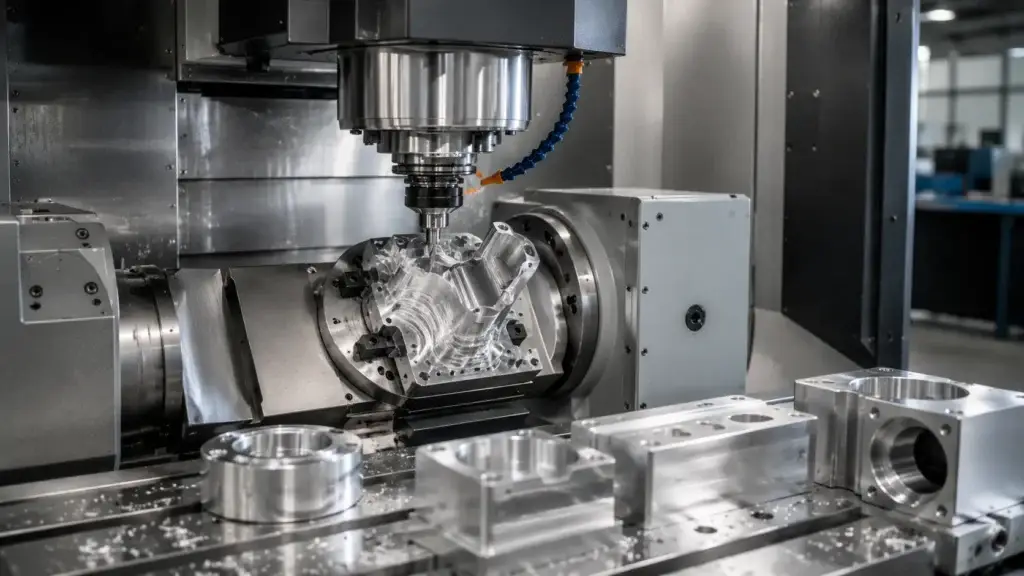
The number of controlled axes affects tool accessibility, setup planning, positional accuracy and cost.
| Machine type | Effect on the process | Typical applications |
| 3-axis milling | Economical for standard geometries but may require additional setups for multiple faces | Plates, brackets, housings and one-direction cavities |
| 4-axis milling | Rotates the workpiece to access side and circumferential features | Side holes, radial features and multi-face components |
| 5-axis milling | Reaches complex angles and surfaces while reducing manual repositioning | Complex contours, deep cavities and multi-angle precision parts |
Five-axis machining is not automatically the best choice for every component. A simple part can often be produced more economically on a 3-axis machine.
Five-axis milling becomes valuable when reducing setups improves access, maintains relationships between multiple features or shortens the overall production sequence. Fewer setups can reduce datum-transfer error, although the machine and programming costs may be higher.
The correct equipment should therefore be selected according to part requirements—not simply according to the highest available axis count.
Key Factors That Affect CNC Milling Quality
| Process factor | Potential problem | Possible result |
| Incomplete drawing requirements | Incorrect interpretation of materials, datums or tolerances | Assembly or functional failure |
| Insufficient DFM review | Impractical walls, cavities or internal radii | Higher cost, deformation or tool failure |
| Poor workholding | Movement or clamping distortion | Dimensional and positional variation |
| Tool wear or runout | Unstable cutting engagement | Size deviation and visible tool marks |
| Incorrect speeds and feeds | Heat, chatter or built-up edge | Poor surface quality and shorter tool life |
| Excessive tool extension | Reduced tool rigidity | Vibration, taper and inaccurate walls |
| Poor chip evacuation | Chips are recut or trapped | Surface scratches and tool damage |
| Thermal variation | Expansion of the part or machine | Loss of tight tolerance control |
| Incorrect datum setup | Features shift relative to one another | Hole-position and assembly errors |
| Inadequate inspection | Important deviations remain undetected | Nonconforming parts reach assembly |
Tolerance capability must always be evaluated in relation to the part’s size, geometry, material, setup and inspection method. Learn more in our guide to CNC machining tolerances.
How the CNC Milling Process Affects Cost and Lead Time?
Material machinability
Materials that produce stable chips and cause less tool wear can generally be machined faster. Hard, abrasive or heat-sensitive materials may require specialized tools, slower parameters or additional process control.
Part geometry
Deep cavities, thin walls, small corner radii and complex surfaces increase programming and machining difficulty. They may require longer tools, smaller stepovers or additional semi-finishing passes.
Number of setups
Every additional setup requires handling, alignment and verification. It also introduces another opportunity for datum-transfer error.
Reducing setups can improve efficiency, but only when the selected machine and fixture provide stable access to all required features.
Tolerances and surface finish
Tighter tolerances and lower roughness values can require:
- Additional finishing passes;
- More frequent tool changes;
- Controlled machining temperatures;
- Slower inspection processes;
- More detailed quality documentation.
Only functionally important features should carry demanding specifications.
Order quantity
For prototypes and small batches, programming and setup costs represent a larger proportion of the unit price. As quantity increases, these initial costs can be distributed across more parts.
However, repeated CNC milling services may require more robust fixtures, planned tool replacement and in-process inspection to maintain batch consistency.
Secondary processing
Heat treatment, anodizing, plating, polishing and special inspection add production stages. If these requirements are identified late, they can cause redesign, dimensional conflicts or longer delivery times.
Common CNC Milling Problems and How to Prevent Them
Chatter and vibration
Chatter can result from excessive tool extension, poor workholding, insufficient machine rigidity or unsuitable cutting parameters.
It can be reduced by shortening tool overhang, improving fixture support, adjusting tool engagement and selecting a more stable cutting strategy.
Thin-wall deformation
Thin sections can move under cutting force, heat or clamping pressure. Deformation may only become visible after the part is released.
Possible controls include balanced material removal, reduced clamping pressure, staged roughing, additional support and leaving temporary reinforcing features.
Burrs and poor edge quality
Worn tools, unsuitable cutting direction and incorrect parameters can create heavy burrs. Tool condition should be monitored, and the machining sequence should account for where burrs will form and how they can be removed safely.
Dimensional variation between batches
Batch variation may come from tool wear, material differences, inconsistent offsets or changing measurement methods.
Standardized setup instructions, tool-life controls, inspection frequencies and measurement procedures improve repeatability.
Poor surface finish
Surface problems may be caused by chatter, runout, built-up edge, recutting chips or an unsuitable finishing toolpath.
The correct response depends on the cause. Simply reducing feed rate may not resolve the problem and can sometimes increase rubbing and heat.
How to Prepare a CNC Milling Project for Quotation?
For an accurate custom CNC milling quotation, provide:
- A STEP, STP, IGES or X_T three-dimensional model;
- A PDF engineering drawing with tolerances and datums;
- Material name and grade;
- Prototype and production quantities;
- Surface roughness requirements;
- Surface treatment and color;
- Critical dimensions and assembly surfaces;
- Hole, thread and insert requirements;
- FAI, CMM or other inspection-report requirements;
- Packaging, labeling and target delivery requirements.
A 3D model alone may not communicate tolerances, thread classes, roughness or inspection datums. Precision parts should normally include both a 3D model and a controlled 2D engineering drawing.
CNC Milling Process FAQs
What are the main steps in the CNC milling process?
The main steps are drawing review, DFM analysis, CAD and datum preparation, CAM programming, material and fixture preparation, machine setup, rough milling, semi-finishing and finish milling, followed by deburring, post-processing and inspection. Each stage affects final accuracy, surface quality, manufacturing cost and lead time.
What is the difference between CAD, CAM and G-code?
CAD defines the geometry and design requirements of the part. CAM determines how the part will be machined, including tools, sequences and cutting parameters. G-code contains the instructions that the CNC controller executes to move the machine and operate the spindle.
What is the difference between rough milling and finish milling?
Rough milling removes a large amount of material efficiently while leaving a controlled allowance. Finish milling removes the remaining allowance to achieve final dimensions, geometric tolerances and surface quality. Semi-finishing may be used between the two stages to create uniform stock.
How accurate is CNC milling?
CNC milling accuracy depends on part size, geometry, material, tolerance type, machine condition, tooling, workholding, temperature and inspection method. Accuracy should be evaluated feature by feature rather than applying one general tolerance to every custom CNC part.
How long does CNC milling take?
The total lead time includes engineering review, programming, material preparation, setup, actual cutting, inspection and any secondary treatment. A geometrically simple part may machine quickly, while deep cavities, multiple setups, tight tolerances and complex reports can extend the project schedule.
What file formats are used for CNC milling?
STEP, STP, IGES and X_T are commonly used for three-dimensional geometry. PDF or DWG drawings are used to communicate tolerances, threads, datums, surface finish and inspection requirements. Providing both formats reduces ambiguity.
When should 5-axis CNC milling be used?
Five-axis milling is suitable when a part contains complex surfaces, deep angled features or multiple faces that are difficult to reach with conventional setups. It can also help maintain positional relationships by reducing workpiece repositioning.
How can CNC milling costs be reduced?
Costs can often be reduced by enlarging internal radii, avoiding unnecessary deep cavities, relaxing noncritical tolerances, standardizing holes and threads, reducing setup directions and clearly identifying critical inspection dimensions. Early DFM review is usually more economical than correcting problems after production begins.
Conclusion
A reliable CNC milling process depends on much more than the cutting equipment. Drawing quality, manufacturability review, datum planning, CAM programming, workholding, tool condition, process control and inspection all contribute to the result.
Preparing complete project information and addressing manufacturing risks before production can reduce unnecessary setups, control cost and improve the consistency of precision CNC milled parts.
SINO-V-RISE provides custom CNC milling services for prototypes, small batches and production components. Our capabilities cover aluminum, stainless steel, brass, copper, titanium, steel and engineering plastics, with 3-axis, 4-axis and 5-axis machining available for different part requirements.
Send us your 3D model, 2D drawing, material, quantity, tolerance and surface-finish requirements. Our engineering team will review the manufacturability of your project and prepare a CNC milling quotation.