
CNC milling tolerances define how much a finished part may deviate from the dimensions, geometry, and feature relationships specified in an engineering drawing. They directly influence whether components assemble correctly, move smoothly, seal reliably, and remain interchangeable during production.
A commonly quoted tolerance for CNC milling machining is approximately ±0.005 in, or ±0.127 mm. However, this value should only be treated as a general reference. The tolerance that can be consistently maintained depends on the material, part size, feature geometry, cutting tools, workholding method, number of setups, surface finishing, inspection method, and production volume.
Certain critical features can be produced to much tighter tolerances through precision CNC milling. However, tighter is not automatically better. Unnecessarily restrictive tolerances increase machining time, inspection requirements, tool consumption, and scrap risk without necessarily improving part performance.
The objective is therefore not to specify the smallest possible tolerance. It is to establish a tolerance that supports the function of the part and can be manufactured and verified consistently.
What Are CNC Milling Tolerances?
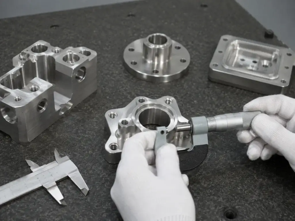
No CNC milling process produces dimensions with absolutely zero variation. Even when the same program, machine, cutting tool, and material are used, small differences occur because of tool wear, thermal expansion, spindle runout, material behavior, workholding, and measurement uncertainty.
A tolerance defines the permitted range within which a manufactured feature is accepted.
For example, suppose a hole is specified as:
25.00 ±0.05 mm
The acceptable limits are:
- Upper limit: 25.05 mm
- Lower limit: 24.95 mm
- Total tolerance zone: 0.10 mm
A measured hole of 25.02 mm is acceptable, while a hole measuring 25.07 mm is outside the specified tolerance.
Several related terms are important:
- Nominal size: The intended dimension shown on the drawing.
- Actual size: The measured dimension of the finished part.
- Upper and lower limits: The largest and smallest acceptable dimensions.
- Deviation: The difference between the actual and nominal dimensions.
- Tolerance zone: The complete permitted range between the limits.
Accuracy and precision are not the same
Accuracy describes how close a measured result is to the target dimension. Precision describes how consistently a manufacturing process reproduces the same result.
A CNC machining process may occasionally produce one highly accurate part but still have poor repeatability across a production batch. Reliable CNC milling capabilities must therefore be evaluated according to both accuracy and process consistency.
Machine positioning accuracy alone also does not represent the final tolerance of CNC milling parts. The completed component reflects the combined effects of the machine, cutting tool, fixture, material, environment, process plan, and inspection system.
What Is a Standard CNC Milling Tolerance?
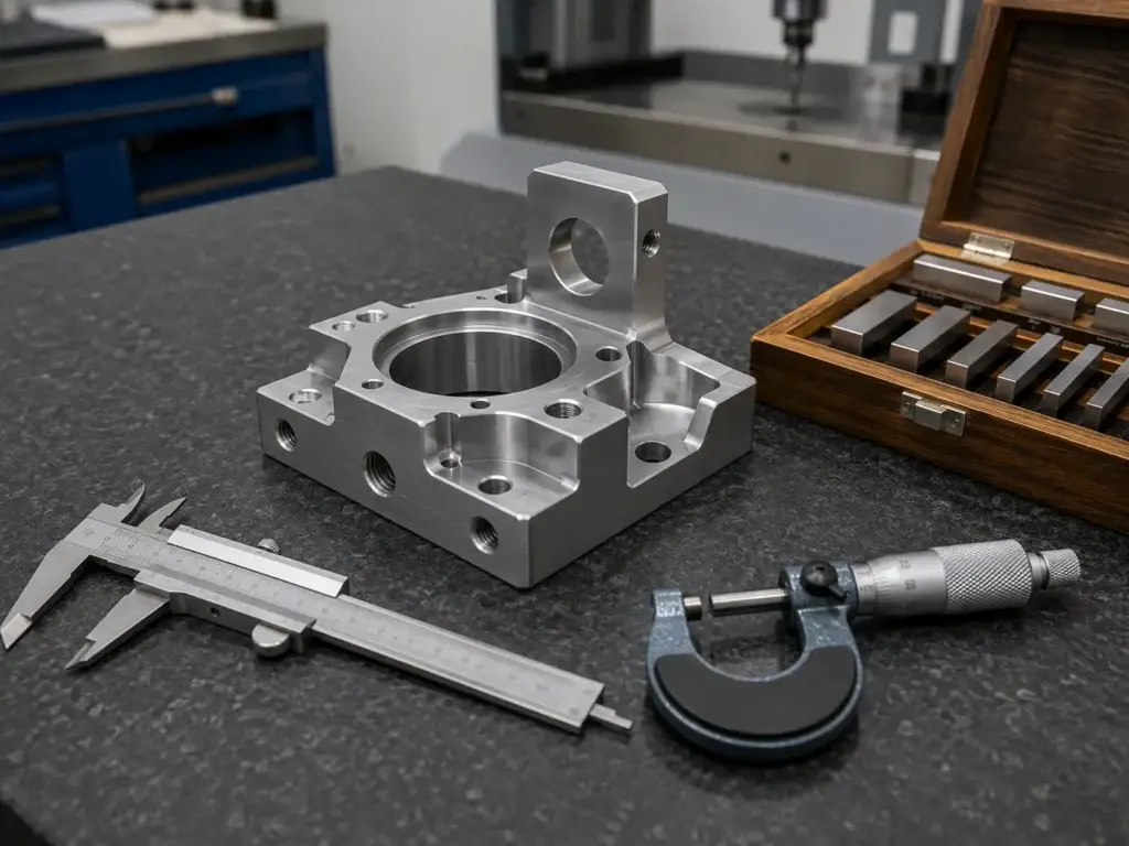
There is no single standard tolerance that applies to every CNC milled component. Many CNC milling companies use an internal default tolerance when a drawing does not specify individual requirements.
For ordinary metal parts, a general reference of approximately ±0.005 in or ±0.127 mm is widely used in the industry. Some suppliers apply metric general tolerances based on ISO 2768 instead.
The appropriate tolerance depends on the type of feature:
- Non-critical external dimensions can usually use general tolerances.
- Mating surfaces and locating features may require precision tolerances.
- Bearing bores, dowel holes and sealing surfaces may require tighter control.
- Deep cavities, thin walls and long parts may need wider tolerances.
- Plastic parts generally require more allowance for thermal expansion and deformation.
- Features produced in separate setups may have greater positional variation.
A standard CNC tolerance should never replace a clear engineering requirement. If a dimension affects assembly, alignment, movement, sealing, safety or service life, it should be identified separately on the 2D drawing.
Standard, Precision and Tight CNC Milling Tolerances
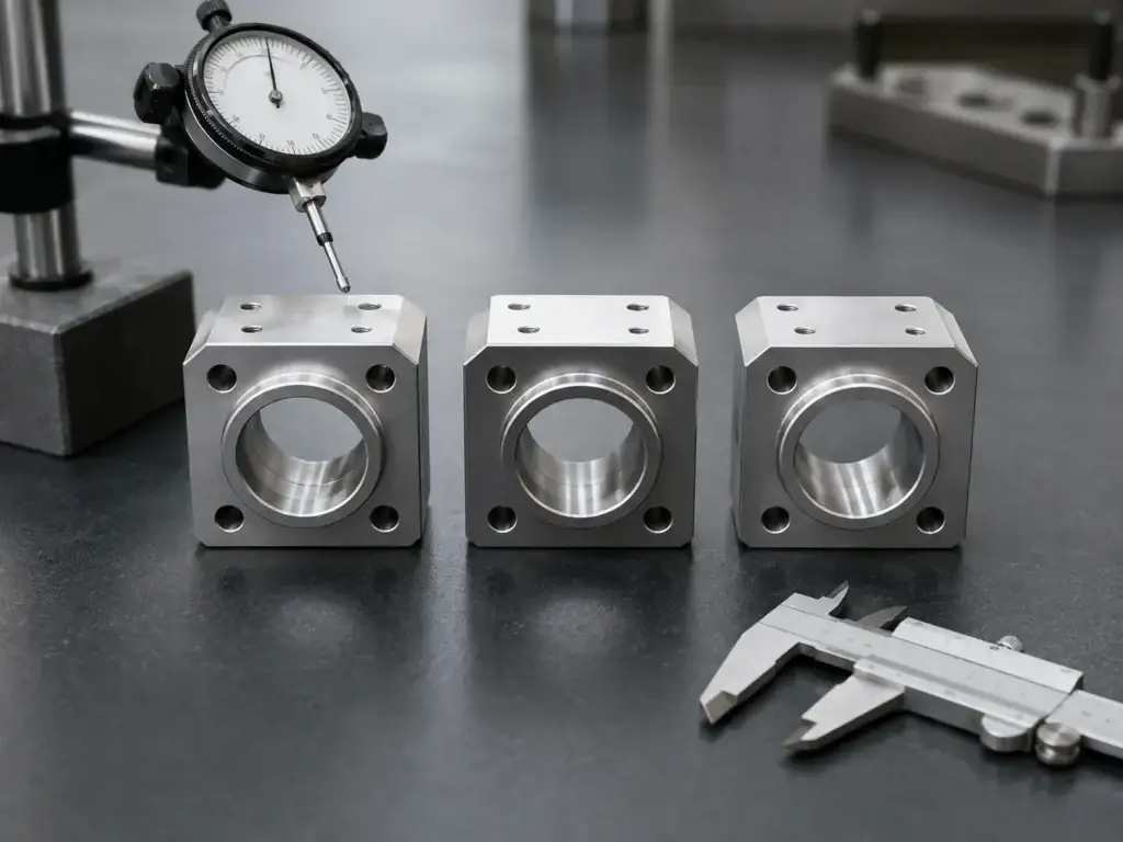
The following categories provide a practical way to discuss tolerance requirements with a CNC milling service provider. They are not universal guarantees because achievable results still depend on the individual feature and production conditions.
| Tolerance level | Typical applications | Production impact | Engineering review |
| General | External profiles, clearance features and non-mating surfaces | Standard machining and inspection | Usually limited |
| Precision | Locating surfaces, assembly dimensions and functional features | Additional finishing passes and inspection | Recommended |
| Tight | Precision fits, sealing areas, bearing bores and critical positions | Controlled tools, fixtures, temperature and measurement | Required |
| Ultra-tight | Optical, medical, motion-control and specialized components | May require grinding, honing, reaming or other secondary operations | Essential |
General tolerances
General tolerances are appropriate for dimensions that do not directly determine how a component fits or functions. Applying a normal tolerance to these features allows a CNC milling manufacturer to use efficient tools, standard machining parameters, and practical inspection methods.
Precision tolerances
Precision CNC milling is commonly required for assembly interfaces, positioning features and surfaces that establish alignment. These dimensions may need dedicated finishing tools, controlled cutting parameters, stable workholding, and more frequent measurement.
Tight tolerances
Tight tolerance CNC machining usually requires a feature-specific process review. A tolerance that is practical on a short, rigid bore may be difficult to maintain on a thin wall, deep pocket or long part.
Ultra-tight tolerances
When the required tolerance approaches the limits of conventional milling, additional processes may be necessary. These can include precision reaming, jig grinding, surface grinding, honing, wire EDM or controlled lapping.
For this reason, a single statement such as “tolerance up to ±0.005 mm” does not fully describe the actual manufacturing capability. The material, geometry, feature type, batch size and inspection method must also be considered.
Types of Tolerances Used in CNC Milling
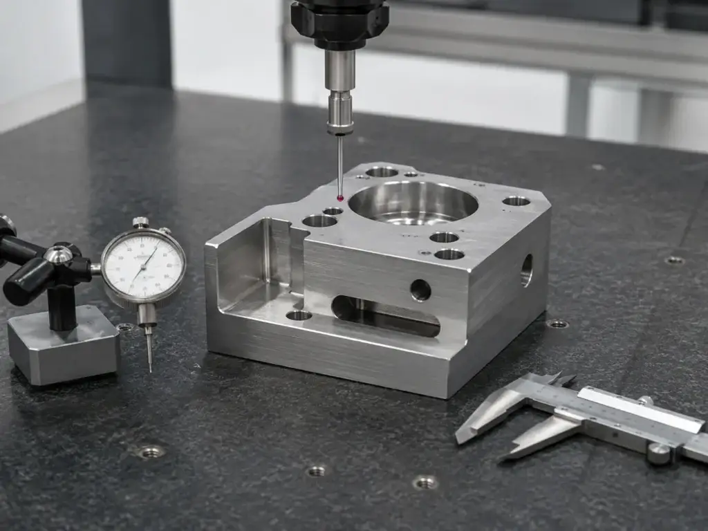
Bilateral tolerance
A bilateral tolerance permits variation in both directions from the nominal dimension.
Example:
40.00 ±0.05 mm
The acceptable range is 39.95–40.05 mm.
This format is suitable when equal variation above or below the nominal size has no negative effect on assembly or performance.
Unilateral tolerance
A unilateral tolerance permits variation in only one direction.
Example:
20.00 +0.00/-0.04 mm
The acceptable size is 19.96–20.00 mm.
This method is useful when exceeding the nominal dimension would interfere with assembly, while a small amount of variation in the opposite direction is acceptable.
Limit dimensions
Limit dimensions show the largest and smallest acceptable values directly.
Example:
24.98–25.02 mm
This format removes the need for the machinist or inspector to calculate the limits from a nominal dimension.
Geometric tolerances
Dimensional tolerances control size, but they do not fully control the shape, orientation or position of a feature. Geometric Dimensioning and Tolerancing, or GD&T, can define requirements such as:
- Flatness
- Straightness
- Parallelism
- Perpendicularity
- Position
- Profile
- Circularity
- Cylindricity
- Runout
For example, two holes may both have acceptable diameters but still fail to align during assembly because their positions relative to the datum are incorrect. A position tolerance is more effective than applying very tight ± coordinate dimensions.
Hole and shaft fits
Mating holes and shafts are often specified using a recognized fit system rather than independent bilateral tolerances. Clearance, transition and interference fits can be defined using ISO 286 classes such as H7/g6 or H7/p6.
The correct fit depends on whether the assembly must slide, locate accurately, transmit torque or remain permanently locked.
ISO 2768 and Other CNC Tolerance Standards
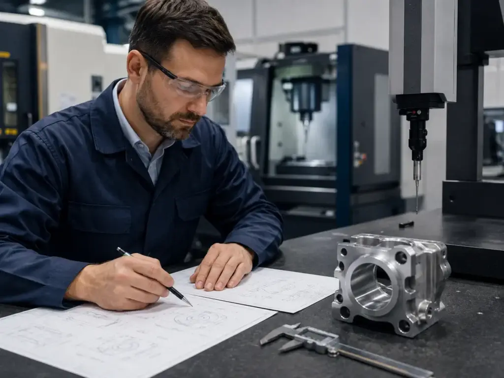
Tolerance standards reduce the need to assign an individual tolerance to every dimension. However, the selected standard must be clearly stated in the drawing title block.
ISO 2768-1
ISO 2768-1 defines general tolerances for linear and angular dimensions without individually indicated tolerances. It includes four tolerance classes:
- f: Fine
- m: Medium
- c: Coarse
- v: Very coarse
For many conventional machined metal parts, ISO 2768-m is used as a practical general tolerance class. The appropriate selection still depends on the part size, manufacturing process and functional requirements.
ISO 2768-2
ISO 2768-2 addresses general geometrical tolerances for features without individual geometric tolerance indications. Its classes are:
- H: Fine
- K: Medium
- L: Coarse
A drawing may therefore state a combined requirement such as ISO 2768-mK.
ISO 2768-2 should not be confused with a surface roughness standard. Surface finish requirements such as Ra 1.6 μm or Ra 3.2 μm must be specified separately where necessary.
ISO 286
ISO 286 is commonly used for limits and fits involving holes and shafts. It helps engineers define clearance, transition and interference relationships for interchangeable components.
ASME Y14.5 and GD&T
ASME Y14.5 provides rules for dimensional and geometric tolerancing commonly used in the United States and international supply chains. It enables designers to control a feature relative to defined datums and functional relationships.
When a general tolerance standard is insufficient
ISO 2768 or another general standard should not be the only requirement when a part includes:
- Bearing or dowel holes
- Precision locating features
- Sealing surfaces
- Critical hole patterns
- Sliding or rotating fits
- Thin-walled functional sections
- Features machined in multiple setups
- Strict surface profile requirements
These features should be individually specified using dimensional tolerances, fits, GD&T and surface finish requirements.
How Part Features Affect Achievable Milling Tolerances?
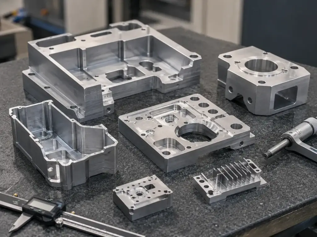
Different features respond differently to cutting forces, heat, tool deflection and fixturing. This is one reason why custom CNC milling parts cannot be evaluated using a single tolerance value.
| Part feature | Main manufacturing risk | Recommended control | Typical inspection |
| Flat surface | Warping, residual stress and uneven clamping | Flatness and thickness | CMM, surface plate or height gauge |
| Hole or bore | Tool wear, taper and runout | Diameter tolerance or fit class | Plug gauge, bore gauge or CMM |
| Hole pattern | Datum transfer and positioning error | Position tolerance | CMM |
| Thin wall | Cutting-force and clamping deformation | Size and profile tolerance | CMM or optical measurement |
| Vertical face | Tool deflection and datum error | Perpendicularity | CMM |
| Sealing face | Distortion and tool marks | Flatness and surface roughness | CMM and roughness tester |
| Deep pocket | Long tool deflection and vibration | Size and profile tolerance | CMM |
| Multi-face feature | Setup and datum-transfer error | Position, parallelism or profile | CMM |
Holes and bores
Drilled holes may be sufficient for general clearance applications. Precision bores may require boring, reaming or circular interpolation followed by controlled measurement.
A hole diameter and its position should be treated as separate requirements. An accurately sized hole may still be unusable if its location relative to the assembly datum is incorrect.
Flat surfaces
Large, thin plates can distort after material removal. Tight flatness requirements may require symmetrical roughing, stress-relieved material, controlled clamping, rest periods between operations, and a final light finishing pass.
Deep pockets
Deep pockets often require long tool extension. Increasing tool length reduces rigidity and increases the risk of deflection, chatter, wall taper and corner variation.
Thin walls
Thin walls can move during cutting and spring back after the fixture is released. Excessive clamping pressure can also distort the part before machining begins.
Strategies may include staged roughing, temporary support, reduced cutting forces, alternating machining sides and leaving finishing stock until the final operation.
Multiple-face features
A feature relationship produced in one setup is generally easier to control than a relationship established across multiple setups. Every new setup introduces possible datum-transfer, locating and clamping errors.
A 4 axis CNC mill or 5 axis CNC mill can reduce repositioning for suitable geometries. However, fewer setups do not automatically guarantee tighter tolerances; machine calibration, workholding, programming and inspection remain essential.
Small internal radii
Internal corners are generated by rotating cutting tools, so the corner radius cannot be smaller than the tool radius. Using an unnecessarily small end mill increases cycle time and tool deflection.
Long components
Long parts are more sensitive to thermal expansion, clamping distortion and machine travel accuracy. Multiple supports and a suitable machining sequence may be necessary.
Freeform surfaces
Profile accuracy on complex three-dimensional surfaces depends on tool geometry, step-over, toolpath calculation, machine dynamics and the method used to inspect the resulting surface.
Factors That Affect CNC Milling Tolerances
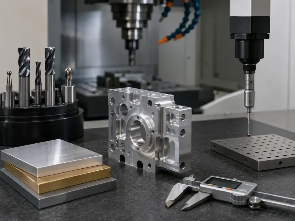
1. Machine condition and positioning
Backlash, guideway condition, spindle performance, servo behavior and machine calibration all influence CNC milling accuracy.
Preventive maintenance and periodic calibration help maintain predictable positioning, but machine specifications alone cannot determine the final part tolerance.
2. Spindle and tool runout
Runout causes the cutting edges to rotate away from the intended centerline. This can create oversized holes, uneven tool wear, poor surface finish and inconsistent wall dimensions.
Clean tool holders, suitable collets, balanced tools and controlled spindle condition help reduce runout.
3. Tool wear
As a cutting edge wears, cutting forces and heat increase. Dimensions may gradually drift across a production batch even though the program remains unchanged.
Tool-life monitoring, scheduled tool replacement, in-process measurement and wear compensation are important for large-volume CNC milling service.
4. Tool deflection
Cutting forces bend the tool away from the programmed path. Deflection becomes more significant with small-diameter tools, long extensions, deep cavities and hard materials.
A rigid tool with the shortest practical extension should be used. Roughing and finishing should also be separated so the final pass removes a controlled and consistent amount of material.
5. Workholding
A fixture must hold the component securely without deforming it. Clamping a thin or soft part too tightly can produce an acceptable measurement while the part is held, followed by distortion after release.
Fixtures should support the component near the cutting area and establish clear, repeatable datums.
6. Material behavior
Different metals and engineering plastics respond differently to cutting heat and force. Hardness, ductility, thermal conductivity, internal stress and moisture absorption all affect achievable tolerances.
Material condition and temper should therefore be defined instead of identifying only the general material family.
7. Cutting heat
Heat changes the dimensions of the cutting tool, workpiece and machine structure. This effect becomes important during long cycles and when producing large or tightly toleranced components.
Stable coolant conditions, controlled machining parameters, machine warm-up routines and temperature stabilization before final inspection can improve consistency.
8. Residual stress
Removing material can release internal stress and cause the component to twist or bow. Extruded plate, rolled stock, forgings and heat-treated materials may behave differently during the CNC milling manufacturing process.
Rough machining, stress relief and delayed finishing may be required for dimensionally sensitive parts.
9. Number of setups
Every setup creates an additional locating relationship. Features produced in different orientations may accumulate alignment errors if datums are not transferred accurately.
Using common datums, qualified fixtures, probing and multi-axis machining can reduce these risks.
10. Surface treatment
Anodizing, plating, powder coating, polishing and other finishing processes can add or remove material. Critical dimensions must be evaluated in the condition in which the part will ultimately function.
11. Measuring method
A tolerance is meaningful only when it can be reliably verified. Calipers are unsuitable for many tight feature relationships, while CMM inspection requires correct datum alignment and a suitable measurement strategy.
12. Production quantity
A prototype may occasionally meet a demanding tolerance through individual adjustment. Holding the same requirement across hundreds or thousands of CNC milling parts requires a stable process, controlled tool replacement, regular measurement and defined reaction limits.
CNC Milling Tolerances by Material
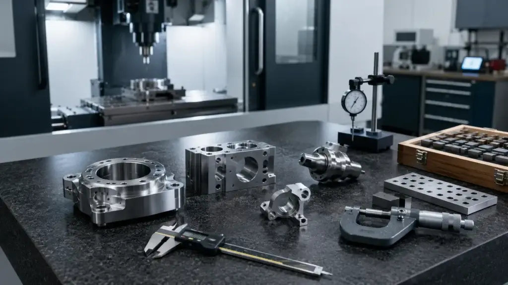
Material selection affects both machinability and dimensional stability. The following characteristics should be considered before final tolerances are assigned.
Aluminum
Aluminum alloys are widely used for precision CNC milling because of their good machinability and relatively low cutting forces. However, thin walls, large pockets and internally stressed stock can still distort.
Grades such as 6061 and 7075 also behave differently. The alloy, temper, stock form and surface treatment requirement should be confirmed during the design review.
Stainless steel
Stainless steel generates more cutting heat and can work-harden if tools rub instead of cutting effectively. Tool wear and deflection can make close dimensional control more difficult, particularly in deep or thin features.
Stable cutting parameters, rigid tooling and planned tool replacement are essential.
Titanium
Titanium has low thermal conductivity, causing heat to remain near the cutting edge. It also produces high cutting forces relative to its machinability.
Precision machining of titanium requires rigid setups, appropriate tools, controlled heat generation and sufficient process time.
Brass and copper
Many brass grades offer good machinability and can produce clean, accurate features. Copper can be more adhesive and may generate burrs or tool loading depending on the grade and condition.
The specific alloy must be considered rather than treating all copper-based materials as identical.
Engineering plastics
Engineering plastics present different challenges from metals:
- Higher thermal expansion
- Lower stiffness
- Sensitivity to clamping pressure
- Moisture absorption
- Dimensional change after machining
- Potential stress relaxation
Materials such as nylon can absorb moisture and change size, while PTFE may deform under moderate pressure. Plastic CNC machining tolerances are therefore often wider than those used for rigid metal components.
How Tight Tolerances Affect CNC Milling Cost?
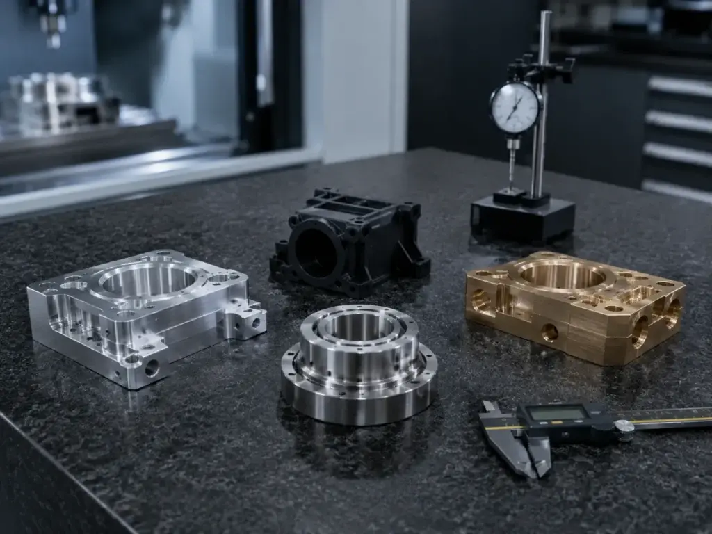
Tight tolerances increase cost because they change the complete manufacturing and inspection process—not simply because the CNC machine must “cut more accurately.”
Additional process planning
Critical features must be identified, datum relationships reviewed, suitable tools selected, and inspection steps incorporated into the manufacturing plan.
More complex workholding
Dedicated soft jaws, fixtures, supports or probing routines may be needed to control deformation and repeatability.
Additional machining passes
A high precision CNC milling process may require separate roughing, semi-finishing and finishing operations. Smaller final cuts are used to control cutting force, heat and dimensional variation.
Reduced cutting speed
Aggressive material removal can increase vibration, heat and deflection. More conservative cutting parameters may therefore be required.
Increased tool consumption
Critical tools may be replaced before reaching their normal wear limit. Finishing tools may also be reserved for particular dimensions.
In-process inspection
Dimensions may need to be measured between operations so that offsets can be corrected before final machining.
Temperature control
Parts may need time to return to a stable temperature before measurement. In demanding applications, machining and inspection environments may also require temperature management.
Advanced final inspection
CMM programming, profile analysis and full-dimensional reporting take more time than a basic caliper inspection.
Higher scrap and rework risk
A smaller tolerance zone leaves less room for normal process variation. A minor change in material, temperature, tool wear or setup can make a component unacceptable.
Secondary operations
Grinding, honing, precision reaming, lapping or wire EDM may be necessary when milling alone cannot consistently achieve the requirement.
The most effective cost-control strategy is to assign tight tolerances only to features that directly influence fit, function, safety or service life.
How Surface Finishing Affects Final Dimensions
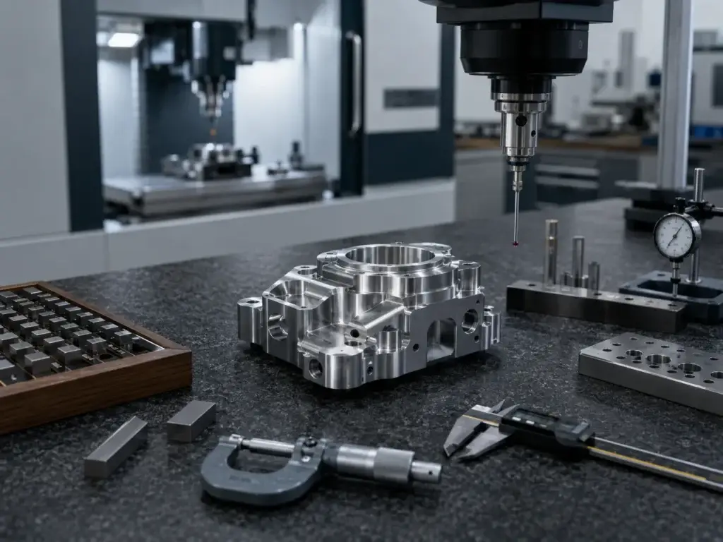
Surface treatment should be considered before machining dimensions are finalized. The drawing must state whether a critical dimension applies before or after finishing.
Anodizing
Anodizing creates an oxide layer on aluminum. Part of the layer grows outward while part penetrates the original surface. The dimensional effect depends on the anodizing type and specified coating thickness.
A precision bore may become smaller after anodizing. Possible solutions include:
- Allowing for coating thickness during machining
- Masking the bore
- Finishing the bore after anodizing
- Specifying the required final dimension after treatment
Plating
Nickel, chrome, zinc and other plated coatings add material to the surface. Thickness distribution may vary with feature geometry, particularly around edges, recesses and internal holes.
Powder coating
Powder coating adds a comparatively thick layer. It is generally unsuitable for untreated precision fits, threads and electrical contact areas unless those features are masked.
Polishing
Polishing removes material. It may alter edges, flatness and local dimensions if excessive material is removed from a functional surface.
Bead blasting
Bead blasting primarily changes texture, but it can affect delicate edges and very fine features. Blasting should be controlled or avoided on critical sealing and sliding surfaces when necessary.
Passivation
Passivation generally has far less dimensional influence than thick coating processes because it cleans and improves the protective surface of stainless steel rather than applying a substantial deposited layer.
Practical example: anodized aluminum bore
Consider an aluminum component with a close-fitting bore:
- The bore is machined to its nominal size.
- Anodizing forms an oxide layer on the bore surface.
- The effective bore diameter decreases.
- The mating component may no longer fit.
- The drawing did not clarify whether the size applied before or after anodizing.
This problem can be prevented by defining the finished condition, coating thickness, masking requirement and final inspection stage before production begins.
How CNC Milling Tolerances Are Inspected?
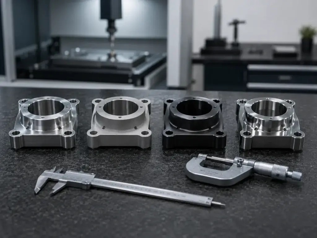
Inspection equipment should be selected according to the feature, tolerance zone and datum relationship.
| Requirement | Inspection equipment | Typical application |
| General length or width | Caliper | Non-critical external dimensions |
| Thickness or outside diameter | Micrometer | Accurate two-point measurement |
| Bore diameter | Bore gauge or plug gauge | Precision holes and production checks |
| Height or step | Height gauge | Features referenced to a flat datum |
| Thread acceptance | Thread plug or ring gauge | Internal and external threads |
| Position, profile or datum relationship | CMM | Complex geometric requirements |
| Small two-dimensional profile | Optical measuring system | Fine contours and small features |
| Surface roughness | Roughness tester | Ra and related texture requirements |
| Flatness | CMM or surface plate method | Mating and sealing surfaces |
First article inspection
First article inspection confirms that the selected material, machine setup, program, tooling, workholding and inspection method can produce a conforming part before full production begins.
In-process inspection
In-process inspection identifies dimensional drift caused by tool wear, temperature change or fixture variation. It enables corrections before an entire batch is completed.
Final inspection
Final inspection verifies the completed components in the required delivery condition, including any specified surface treatment.
CMM and full-dimensional reports
A CMM is particularly valuable for evaluating feature position, profile, perpendicularity, parallelism and datum relationships. When required, a full-dimensional report can document the measured results for every specified drawing characteristic.
Measurement uncertainty
An instrument should provide sufficient accuracy and resolution relative to the tolerance being inspected. A measuring device whose uncertainty is close to the complete tolerance zone cannot reliably determine whether the feature conforms.
Calibration status, measurement temperature, inspection fixtures and datum alignment must also be controlled.
Design Tips for Specifying Practical Tolerances
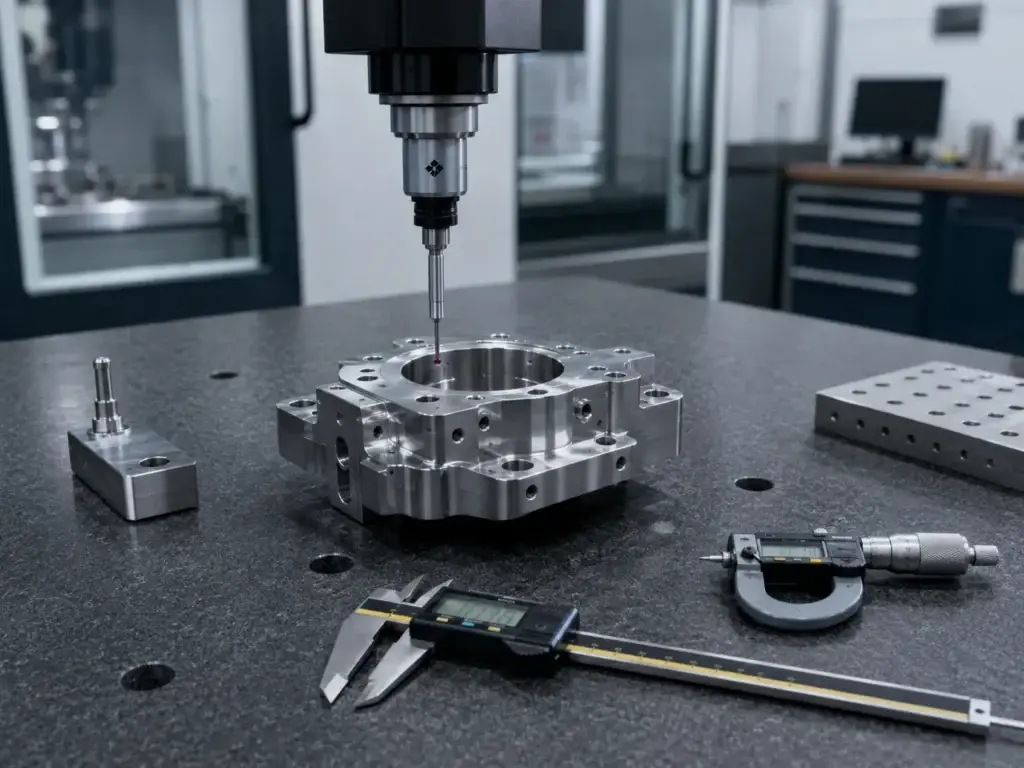
1. Apply tight tolerances only to functional features
Identify which dimensions influence assembly, movement, sealing, alignment, safety or interchangeability. General profiles and clearance surfaces rarely need the same level of control.
2. Define clear datums
Datums establish how the component is located for machining and inspection. Functional datums should reflect how the part interfaces with the final assembly.
3. Provide a 2D engineering drawing
A 3D model communicates geometry but usually does not fully define:
- Dimensional tolerances
- GD&T
- Datums
- Surface roughness
- Thread classes
- General tolerance standards
- Inspection requirements
- Finished-condition dimensions
A controlled 2D PDF drawing should accompany the 3D model.
4. Use general tolerances for non-critical dimensions
A standard such as ISO 2768 can simplify the drawing and prevent unnecessary individual tolerances. Critical features should still be identified separately.
5. Select suitable hole and shaft fits
Use a recognized fit system when two components must slide, locate, rotate or lock together. Avoid assigning arbitrary hole and shaft tolerances without checking the resulting clearance or interference.
6. Analyze tolerance stack-up
Several individually acceptable dimensions can accumulate into an unacceptable assembly condition. Tolerance stack-up analysis is especially important for chains of holes, spacers, shoulders and mating surfaces.
7. Define the finishing condition
State whether critical dimensions apply before or after anodizing, plating, coating or polishing. Identify surfaces that require masking.
8. Avoid unnecessary tight tolerances on difficult features
Thin walls, deep pockets, long unsupported sections and small internal radii are more sensitive to deflection and distortion. Tight requirements should be applied only when functionally necessary.
9. Confirm the inspection method
Discuss how the supplier will measure the most critical characteristics. The drawing, manufacturing method and inspection plan should use consistent datums.
10. Complete first article approval before production
For custom CNC milling parts, first article approval provides an opportunity to confirm functional dimensions, appearance, documentation and inspection methods before batch manufacturing.
Information to Provide for a CNC Milling Quote
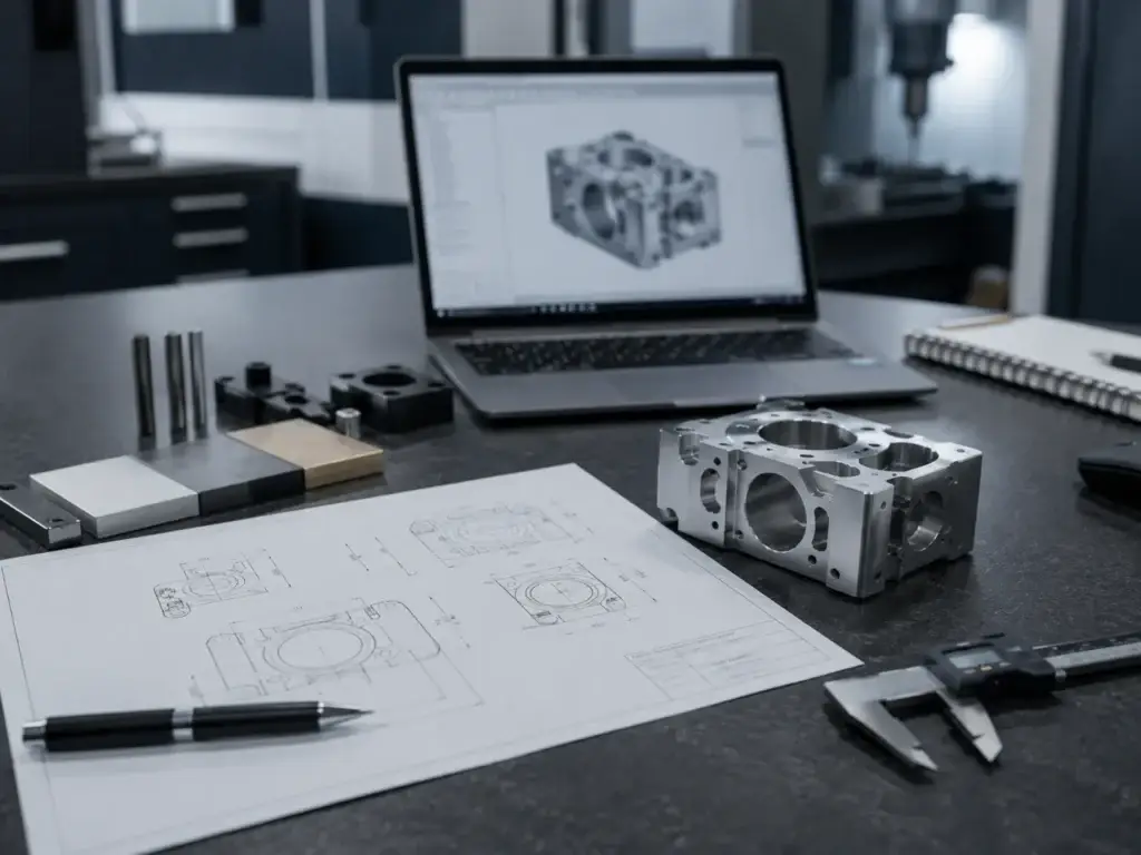
A complete request for quotation allows a custom CNC milling manufacturer to evaluate cost, feasibility, tolerance risk and delivery time more accurately.
Provide the following information:
- STEP, STP, IGES, Parasolid or another suitable 3D file
- Controlled 2D PDF engineering drawing
- Material grade and condition
- Required quantity
- Critical dimensions and tolerances
- GD&T symbols and datum definitions
- Hole and shaft fit requirements
- Thread specifications
- Surface roughness requirements
- Heat treatment
- Surface finishing and coating thickness
- Dimensions that apply after finishing
- First article or sample requirements
- CMM or full-dimensional report requirements
- Material and finishing certificates
- Packaging requirements
- Target delivery schedule
Whether the part requires 3 axis CNC milling, multi-sided machining, a 4 axis CNC mill or 5 axis CNC mill should be determined from its geometry and tolerance relationships—not simply from the perceived capability of the machine.
An experienced CNC milling factory can review the files and recommend a practical machining and inspection plan before production begins.
CNC Milling Tolerance FAQs
What is a standard tolerance for CNC milling?
Approximately ±0.005 in, or ±0.127 mm, is commonly used as a general industry reference for ordinary machined metal dimensions. However, actual standard tolerances vary by supplier, part size, material and feature type. The applicable general tolerance should be clearly stated on the engineering drawing.
Is ±0.005 mm achievable with CNC milling?
It may be achievable for certain small, rigid and accessible features under controlled conditions. It should not be treated as a general tolerance for an entire part. Material behavior, tool runout, thermal stability, workholding, geometry, batch quantity and inspection capability must be reviewed before production.
What is considered a tight CNC machining tolerance?
A tolerance is considered tight when it requires substantially more control than the supplier’s normal machining process. There is no universal numerical boundary. A tolerance that is straightforward for a short precision bore may be difficult for a thin wall, deep cavity or long multi-setup component.
Does 5-axis milling improve tolerance?
A 5 axis CNC mill can reduce the number of setups and help maintain relationships between features machined from different directions. However, 5-axis machining does not automatically guarantee tighter tolerance. Machine calibration, fixture rigidity, tool condition, programming and inspection remain decisive factors.
Why are plastic CNC tolerances usually wider?
Engineering plastics generally have higher thermal expansion, lower stiffness and greater sensitivity to moisture and clamping pressure than metals. They can change dimensions during machining, after fixture release or as environmental conditions change.
How do tight tolerances affect CNC milling cost?
Tight tolerances may require additional process planning, dedicated fixtures, slower cutting parameters, more finishing passes, earlier tool replacement, in-process measurement, CMM inspection and higher scrap allowances. Secondary finishing processes may also be necessary.
Is a 3D model enough to specify tolerances?
Usually not. A 3D model defines the part geometry, but a 2D engineering drawing is normally required to communicate dimensional tolerances, GD&T, datums, surface roughness, fits, threads, general standards and inspection requirements.
How are CNC milling tolerances inspected?
General dimensions may be inspected using calipers, micrometers, height gauges and plug gauges. Complex position, profile and datum-related requirements are normally evaluated using a CMM or an appropriate optical measurement system.
Does anodizing affect part dimensions?
Yes. Anodizing creates an oxide layer on aluminum surfaces and can change the effective size of bores, external profiles and mating features. Critical dimensions should be defined as applying either before or after anodizing, with masking or machining allowance specified where necessary.
What is the difference between dimensional tolerance and GD&T?
Dimensional tolerance controls the acceptable variation in feature size or distance. GD&T controls geometric characteristics such as form, orientation, position and profile relative to defined datums. Both may be required to ensure that a part assembles and functions correctly.
Conclusion
Successful tolerance control begins before the CNC milling machine starts cutting. It requires the designer and manufacturer to connect part function with material behavior, feature geometry, machining strategy, surface treatment and inspection capability.
General tolerances are appropriate for non-critical dimensions, while tighter requirements should be reserved for features that determine fit, alignment, sealing, motion or interchangeability. This approach improves manufacturability, supports stable batch production and avoids unnecessary machining costs.
SINO-V-RISE provides custom CNC milling services for prototypes and small-batch precision parts, covering CNC milling machining, multi-axis manufacturing, material selection, surface finishing and dimensional inspection. Our team can review your 3D models and engineering drawings to identify tolerance risks and develop a suitable manufacturing plan.
Send us your 3D files, 2D drawings, material specifications, quantities and inspection requirements to discuss your custom CNC milling project.