

Five Axis CNC Machined Aluminum Perforated Bell
Perforated bells machined on five-axis centres from 6061-T6, with a contoured inner profile held to ±0.05 mm, a 2.5 mm wall, 6 to 24 radial slots at ±0.1° and every slot edge broken 0.3 mm inside and out before anodizing.
- Radial Slots on True Centres
- Inner Contour Within 0.05 mm
- Wall Kept at 2.5 mm
- Slots Deburred Inside and Out
*Send the flow or media requirement and the model. Wall thickness at the slot root is what fails first on a rotating bell, and a nominal 2.5 mm wall cut from a drawing often ends up at 2.1 mm at the root.
Five Axis Perforated Bell Overview
A perforated bell is a thin shell with slots in it. The slots have to sit on true radial centres and the wall has to stay even, otherwise the part runs out of balance and the flow through the slots is uneven.
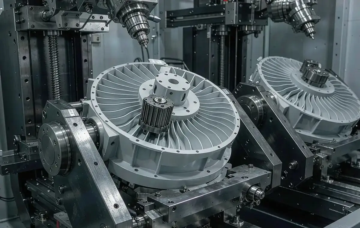
The outside is turned, the inner contour is finished on five axes with a tapered tool, the slots are cut with a 3 mm end mill on a tilted axis, and the part is checked for balance on a mandrel before anodizing.
6061-T6 Aluminium
6061-T6 keeps a 2.5 mm wall stiff enough to hold its shape at speed and machines cleanly at the slot root, where a softer alloy would burr and need hand work that changes the slot width.
7075-T6 or 5052
7075-T6 is used where the bell spins fast and the slots concentrate stress, and 5052 is chosen when the bell is formed from sheet rather than cut from solid.
Below a 2.5 mm wall at the slot root the bell deforms when the last slot is cut, and the contour that measured 0.05 mm closes to 0.15 mm out of round.
Perforated Bell Specifications
Five-axis contouring and slotting data for thin shells, with the wall and slot values that keep a bell balanced.
| Specification | Machining Data | Specification | Machining Data |
|---|---|---|---|
| Product | Perforated Bell / Slotted Cone Shell | Machining Process | 5-Axis Simultaneous Milling, Turning |
| Material | 6061-T6 Aluminium | Envelope | Ø 60 – 140 mm, 55 – 120 mm Deep |
| Inner Contour | ±0.05 mm to the Model | Wall Thickness | 2.5 mm ±0.10 mm |
| Radial Slots | Width ±0.05 mm, Angular Position ±0.1° | Slot Count | 6 – 24 per Bell |
| Holes | Ø 3 – 8 mm, Position ±0.10 mm | Edge Break | 0.3 mm Inside and Outside |
| Concentricity | 0.03 mm Shell to Bore | Base Flange | Square to the Axis Within 0.05 mm |
| Weight | 120 – 460 g | Coating Build | 15 – 20 µm Anodizing |
| Customization | Slot Pattern, Colour, Flange Holes, Logo on the Base | Lead Time | 8 – 11 Days Sample, 16 – 24 Days Batch |
| Inspection | CMM Scan of the Contour, Slot Position Check, Balance Check | Packing | Foam Nest, Individual Box |
How These Bells Are Machined
Turned outside, five-axis inside, slots cut on tilt, balanced before coating.
Inner Contour on Five Axes
The inside is finished with a tapered tool normal to the surface, so the wall stays within 0.10 mm of nominal all the way from the base to the lip instead of thinning where a three-axis tool leans over.
Slots Cut on a Tilted Axis
Each slot is milled with the tool tilted so the flutes cut the full depth in one pass, which leaves a square slot edge instead of the taper a vertical cut produces.
Deburred Inside and Outside
Slot edges are broken 0.3 mm on both faces with a back-deburr tool, because a burr on the inner edge changes the flow and a burr on the outer edge throws the balance off.
Balanced on a Mandrel
Each bell is spun on a mandrel and corrected by removing material from the base flange, not from the slots, so the slot pattern stays as designed.
Bell with slots that must run true?
Finishes for Perforated Bells
Colour is usually functional: visibility outside, low reflection inside.
| Finish | Main Purpose | Finish | Main Purpose |
|---|---|---|---|
| Red Anodizing | High visibility on a rotating part | Clear Anodizing | Natural finish for inspection |
| Black Anodizing | Low reflection inside a housing | Hard Anodizing | Wear face where media passes |
| Bead Blasting | Even matte before dyeing | Masked Bore | Bore stays at fit size |
| Two-Tone Dye | Colour inside the slots only | Laser Marking | Slot count and balance mark |
| Balance Check | Runout under 1 g at the rim | Edge Break | 0.3 mm on every slot edge |
| Salt Spray | 500 h on 6061 | Balance Recheck | After Coating on the Mandrel |
*Dye does not reach the inside of a 3 mm slot evenly; the bell is anodized before the last 0.2 mm of slot width is opened if the internal colour has to be uniform.
Put your CNC milling parts into production today
All information and uploads are secure and confidential.
Trusted for Precision CNC Machined Components
Supporting OEM projects with accurate machining, flexible production, and reliable component quality.
Trusted for Precision CNC Milling.
Machining a Perforated Bell
The slots and the inner contour are cut in the same five-axis pass, so the wall stays 2.5 mm all the way round instead of thinning where the tool leans.
01. Model and Wall Review
Check the inner contour, slot count and wall thickness at the root, then confirm the blank size leaves enough material to hold the part while the slots are cut.
02. Turn the Outside
Turn the outside diameter, the base flange and the bore, leaving 0.4 mm inside for the five-axis finish and marking the slot datum on the flange.
03. Finish the Inner Contour
Rough the inside in three-axis steps, then finish on five axes with a tapered tool normal to the surface, checking wall thickness ultrasonically at four points.
04. Cut and Deburr the Slots
Mill each slot on a tilted axis, break both edges with a back-deburr tool, and blow out the chips between slots so the next cut does not recut them.
05. Balance, Anodize, Box
Spin the bell on a mandrel, correct the flange, mask the bore, anodize, then pack in a foam nest so the thin wall does not take a set in transit.
Send the model and the flow requirement, and we will quote a bell with the contour finished on five axes and the balance checked before coating.
Perforated Bell FAQs
2.5 mm at the slot root for a 140 mm bell. Below that the part deflects when the last slots are cut and the contour goes out of round by 0.1 mm or more.
±0.05 mm with a 3 mm carbide end mill on a tilted axis. A vertical cut on a curved wall gives a slot that is 0.05 mm wider at the outside face.
On a mandrel at the finished diameter, corrected by facing the base flange. Material is never removed from between the slots, because that changes the flow pattern.
140 mm diameter by 120 mm deep on a five-axis centre with a 300 mm table. Larger bells are made in two halves and joined at a flange.
About 20 µm per wall, so a 3 mm slot becomes 2.96 mm. Where the slot width is critical the part is cut 0.02 mm wide and the slots are masked.
Yes, any pattern that can be modelled. We check that no two slots come within 3 mm of each other, since closer than that the wall between them distorts during machining.
Other CNC Machined Mechanical Components
Explore additional precision CNC machined components manufactured for OEM applications and customized production needs.
CNC machined 6061-T6 aluminium control levers with a machined pivot bore, a tapered grip section and a cable slot, held to a.
CNC turned 6061-T6 aluminium rod end joint fittings with a threaded stem, a cross-drilled eye and a flat-faced fork, anodized in.
CNC turned and milled 6061-T6 aluminium timing belt pulleys with HTD 3M, 5M and 8M tooth profiles, bores to H7, runout 0.02 mm.
CNC turned alloy steel threaded flange bases with an internal thread concentric to the spigot, flange face square to 0.02 mm, and.
CNC machined aluminium robot mounting brackets supplied as matched pairs, right-angle held to 0.05 mm, gusseted for stiffness and.
Get high‑quality machined parts in as fast as 4 days with our expanded automated CNC milling!