


Home / CNC-Machining / CNC Milling / CNC Machined Aluminum Circular Positioning Base
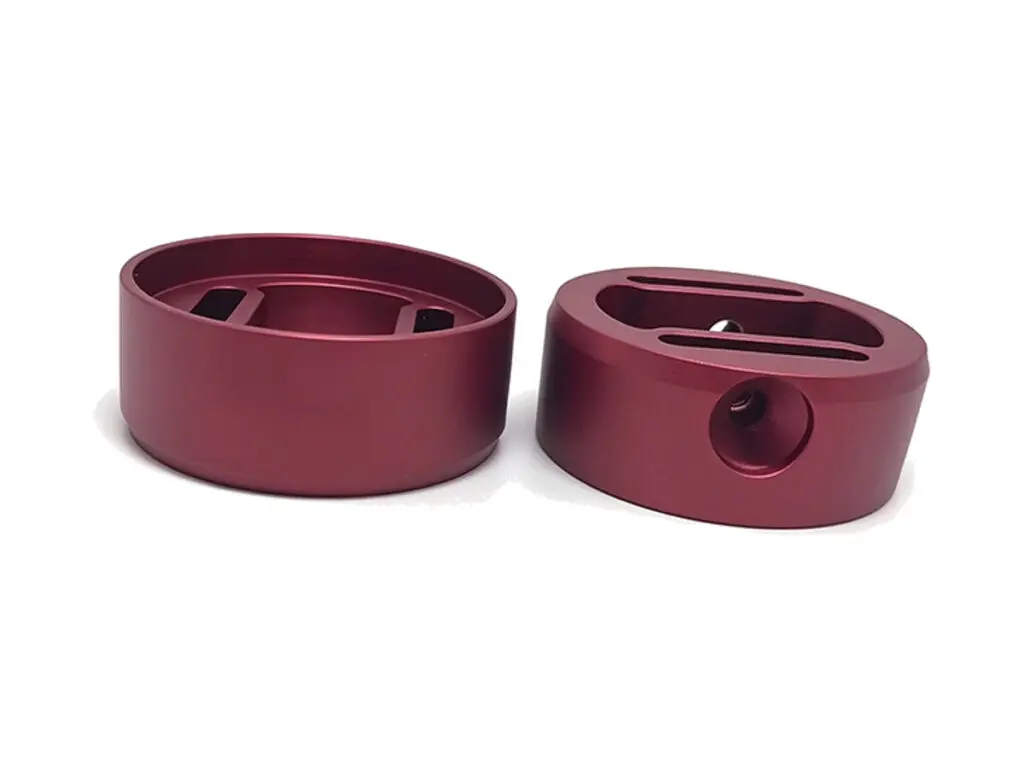
Red anodized aluminium circular positioning bases with a turned register and a drilled bolt circle

CNC Machined Aluminum Circular Positioning Base

CNC machined aluminium circular positioning bases for vision fixtures, rotary stations and robot tooling, with a turned register held to h7, a bolt circle positioned within ±0.02 mm and both faces flat to 0.02 mm. Machined in 6061-T6 and anodized red or black for station identification.

*Tell us which face is the datum and whether the register is a press fit or a locating clearance. A register that is 0.01 mm tight will still seat, but it will not come off again without a puller.

Circular Positioning Base Overview

A positioning base is a reference surface, so its job is repeatability rather than strength. Two fixtures swapped on the same base have to land within a few hundredths of a millimetre, and that depends on the register diameter, the flatness of the seat and the position of the bolt circle relative to the register.

The disc is turned first to establish the register and the seating face on one axis, then the bolt circle and any slots are milled from the same centre. Because the register is turned rather than milled, it stays round within 0.015 mm, which is what keeps a fixture from rocking on the base.

CNC milling of a lightening hole cover plate, a pneumatic manifold block and a sensor enclosure
6061-T6 aluminium round bar stock for CNC turning

6061-T6 Aluminium Disc

6061-T6 is used for fixture bases because it is stable after machining, takes an even dye and is light enough to swap by hand. It holds a turned register without springing, provided the disc is faced on both sides first.

7075-T6 aluminium round disc blank for CNC machining

7075-T6 or Cast Tooling Plate

7075-T6 is chosen for bases that carry a heavy fixture or see repeated clamping loads. Cast tooling plate is the alternative when flatness matters more than strength, because it is stress-relieved and moves less after machining.

If the base is machined from rolled plate, both faces are skimmed to release internal stress before the register is turned; skipping that step is what makes a base go concave after anodizing.

Circular Positioning Base Specifications

Turning and milling data for circular fixture bases, with the register, bolt circle and flatness values that set repeatability.

SpecificationMachining DataSpecificationMachining Data
ProductCircular Positioning Base / Fixture PadMachining ProcessCNC Turning, Then Mill Bolt Circle and Slots
Material6061-T6 Aluminium Plate or DiscRegister Diameter Toleranceh7 (0 / −0.021 on 30 mm)
Diameter Range40 – 300 mmBolt Circle Position±0.02 mm
Thickness8 – 40 mmFace Flatness0.02 mm Across the Register Face
Register Height2 – 10 mmParallelism of Faces0.02 mm
Bolt Pattern3 to 12 Holes, M4 to M10, Slotted on RequestConcentricity Register to OD0.015 mm
Surface FinishRa 1.6 µm Register, Ra 3.2 µm BodyAnodizingType II 15 – 20 µm, Red or Black
CustomizationDiameter, Register Step, Slot Pattern, EngravingLead Time6 – 8 Days (Sample), 12 – 16 Days (Batch)
InspectionCMM Bolt Circle, Flatness on Granite, Register GaugePackingFoam Interleaved, Bagged, Carton

Key Features of Our Positioning Bases

Turned for roundness, milled for position, anodized for identification.

Turned Register, Not Milled

The register is turned on the same axis as the seating face, so it stays round within 0.015 mm and the fixture cannot rock on a high spot.

Bolt Circle From the Same Centre

Bolt holes are milled from the register centre rather than from the outside edge, so the pattern stays concentric even when the OD is machined to a loose tolerance.

Both Faces Stress-Relieved

Plate is skimmed on both sides before the register is cut, which releases rolled-in stress and keeps the base flat after anodizing.

Station Marking Built In

Station numbers or a bolt circle index are laser marked into the anodized face so an operator can identify the base without a label that peels off.

Need a base that repeats to a few hundredths?

Surface Finishes for Positioning Bases

Anodizing changes the register by a few microns, so any fit that matters is either masked or cut oversize.

FinishMain PurposeFinishMain Purpose
Type II AnodizingColour coding for fixture families and general wearHard AnodizingWear face where parts slide across the base
Bead BlastingUniform matte so the dyed colour reads evenLaser MarkingStation number and bolt circle on the top face
Chromate ConversionConductive path when the base is groundedMasked AnodizingKeeps the register bare where a press fit is required

*Registers that are press fits are masked before anodizing or machined 0.02 mm oversize and finished after dye. Unmasked registers lose about 0.015 mm of clearance on a 30 mm diameter.

logo

Put your CNC milling parts into production today

All information and uploads are secure and confidential.

Trusted for Precision CNC Machined Components

Supporting OEM projects with accurate machining, flexible production, and reliable component quality.

Mechanical Equipment Customer
The register was concentric with the bolt circle, so the fixture centres itself without dialling in.

Industrial Components Buyer
Bolt holes lined up with the mating plate without reaming, and the dowels went in by hand.

Equipment Manufacturer
Flatness held after anodizing, so the base sits without rocking on the granite.

OEM Customer
OEM Customer
They matched the red dye across both halves of the order, which we could not get before.

Automation Industry Customer
The customized machining solution provided the dimensional accuracy required for our rotating equipment components.
Trusted for Precision CNC Milling.

Machining Process for Positioning Bases

The register, the bolt circle and the seating face are cut from one datum, so a fixture dropped on the base lands in the same place every time.

01. Interface Review

Check the register diameter, the fixture interface and the bolt pattern against the drawing, and confirm whether the register is a locating fit or a press fit.

02. Disc Preparation

Cut the disc oversize, face both sides to release stress, then re-face the datum side and mark it, since the register and bolt circle are both cut from that face.

03. Turn the Register

Turn the OD and the register step in one set-up, holding the register to h7 and checking roundness with a micrometer at three points.

04. Mill the Bolt Circle

Clamp on the register face, mill the bolt holes and slots from the centre, then deburr and break the edges by 0.3 mm.

05. Anodize, Inspect and Pack

Mask the register where required, anodize to colour, check the bolt circle on a CMM and flatness on granite, then pack with foam between parts.

Send the fixture interface drawing and the station layout, and we will quote the base with the register fit and finish already specified.

Circular Positioning Base FAQs

Within 0.015 mm concentricity between the register and the turned axis, and within ±0.02 mm for the bolt circle. A fixture located on the register and bolted through the circle will repeat inside 0.03 mm over repeated swaps.

Mask it if the fixture is a press fit, because anodizing adds 7 to 10 µm per surface and tightens the fit. For a locating clearance the coating can stay, since 0.01 mm does not affect location.

Yes, and slots are milled in the same set-up as the bolt circle so their centre lines stay radial. Slots let one base accept two fixture variants but cost some repeatability, so they are only used where adjustment is needed.

Yes, if both faces are skimmed before the register is turned. Rolled plate carries internal stress, and a base machined from one side only will bow by 0.05 mm or more once the top face is removed.

From 40 mm to 300 mm diameter, with thickness from 8 to 40 mm. Above 300 mm the part is milled rather than turned, because the register can be interpolated more accurately than it can be swung on a lathe.

Parts are interleaved with foam, bagged individually and packed so the register faces do not touch. Scuffed anodizing cannot be touched up, so packing is treated as part of the finish specification.

Other CNC Machined Mechanical Components

Explore additional precision CNC machined components manufactured for OEM applications and customized production needs.

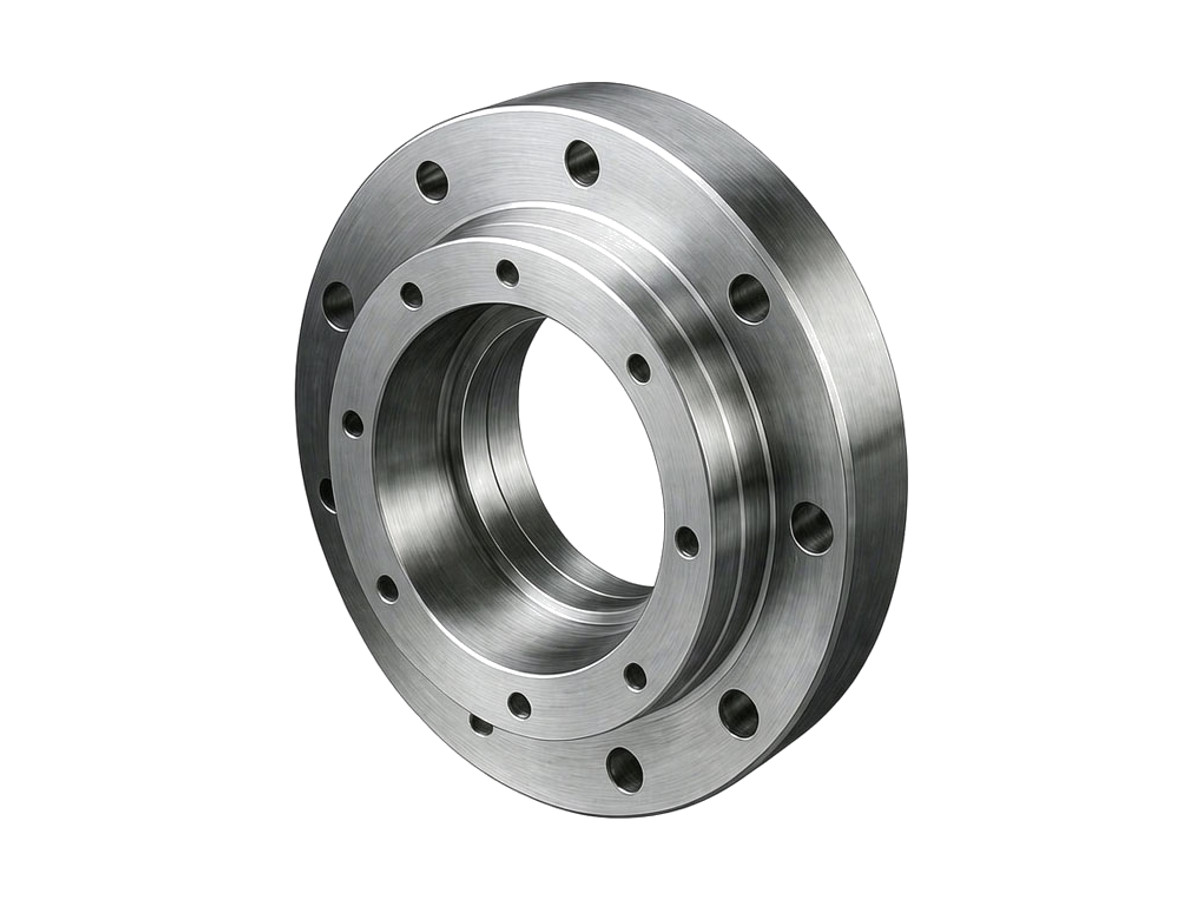
Precision CNC machined steel locating flanges for robot joints.

Precision CNC machined aluminum multi hole fixture plates with a lapped grid of locating holes.

Custom CNC machined aluminum motor housings with bored bearing seats, cooling fins and mounting flanges.

Custom CNC machined aluminum hollow sleeve connectors for robot arm segments and linear modules.

Custom CNC machined aluminium brake booster check valve bodies for motorcycles and automotive systems.

Get high‑quality machined parts in as fast as 4 days with our expanded automated CNC milling!

Scroll to Top