


Home / CNC-Machining / CNC-Turning / CNC Turned Stainless Steel Stepped Axle Pin
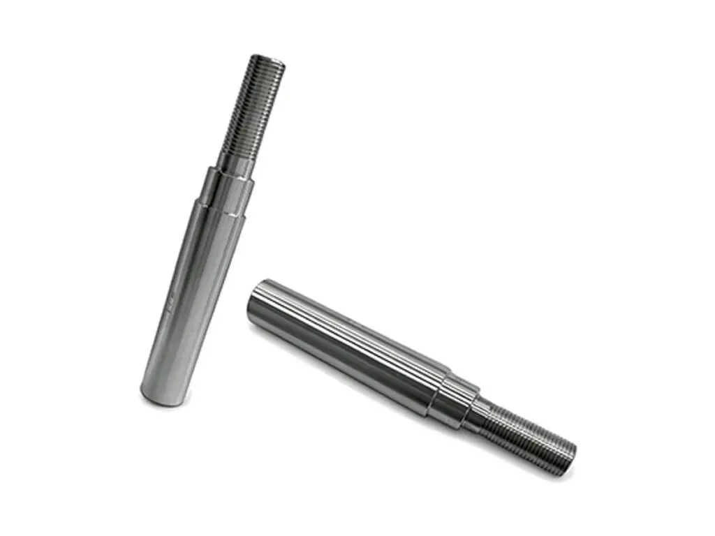
CNC turned stainless steel stepped axle pin with ground journals and a cross hole

CNC Turned Stainless Steel Stepped Axle Pin

Stepped axle pins turned and ground from 316L stainless, with journals to h6 round to 0.005 mm, steps concentric within 0.01 mm, straightness of 0.02 mm over the full length and cross holes deburred from both sides before passivation.

*Send the reamed hole size and the circlip groove position. A journal ground to nominal for a hole that was reamed 0.02 mm oversize will rattle, and no amount of chamfer will fix the play.

Stepped Axle Pin Overview

A stepped pin locates two parts and takes a shear load: the journals have to be round and on one axis, the shoulder has to be square so the parts clamp, and the cross hole has to be deburred or it cuts the retaining clip.

The pin is turned with 0.3 mm on the journals, heat treated if required, then ground between centres so every journal shares one axis before the flats and the cross hole are cut.

Workshop production of a stainless steel stepped axle pin
304L stainless steel round bar stock for CNC machining

316L Stainless Steel Bar

316L is used for pins in wet or washdown equipment because it does not need plating, and it work hardens to a surface that resists fretting in a bushing without a heat treatment.

304L stainless steel plate and block stock for CNC machining

17-4PH or 303 Stainless

17-4PH is chosen where the pin is highly loaded and can be aged to 40 HRC, and 303 where the pin is small, not highly loaded and the free-machining grade keeps the cost down.

For a pin that sees reversing load, 17-4PH at 40 HRC outlasts 316L by a factor of three; for a static locating pin, 316L is enough and does not need a coating.

Stepped Axle Pin Specifications

Turning and grinding data for stepped pins, with the journal, step and straightness values that decide whether the pin goes in by hand.

SpecificationMachining DataSpecificationMachining Data
ProductStepped Axle Pin / Clevis PinMachining ProcessCNC Turning, Grinding, Milling, Cross Drilling
Material316L Stainless Steel BarEnvelopeØ 6 – 60 mm, Length 30 – 300 mm
Journal Diameterh6, Roundness 0.005 mmStep Concentricity0.01 mm
Step Length±0.05 mmShoulder Squareness0.02 mm
Cross HoleØ 2 – 10 mm, Position ±0.1 mmFlatsAcross Flats ±0.05 mm
Surface FinishRa 0.4 µm Journals, Ra 1.6 µm BodyChamfer0.5 × 30° Both Ends
Straightness0.02 mm over the Full LengthHardnessCold Worked, 90 HRB Typical
CustomizationThreaded End, Groove for a Circlip, Head, Drilled Head, PassivationLead Time5 – 7 Days Sample, 12 – 16 Days Batch
InspectionMicrometer Journals, Concentricity Between Centres, Pin Gauge Cross HolePackingOil Paper, Tube, Boxed

Key Features of Our Stepped Pins

Ground between centres, steps from one axis, cross holes deburred.

Journals Ground Between Centres

All journals are ground in one set-up, so they share an axis within 0.01 mm and the pin slides through two bushes without a tight spot in the middle.

Shoulders Square to 0.02 mm

Each shoulder is faced square, so the clamped part sits flat against it and the pin does not bend when the nut is tightened.

Cross Holes Deburred Both Sides

The cross hole is deburred from both ends by hand after drilling, because a burr inside the hole will cut a retaining clip on the first assembly.

Lead-In Chamfer on Every Step

Every step has a 0.5 × 30° lead-in, which is what lets a pin go into a reamed hole by hand instead of being tapped in with a mallet.

Pin that has to slide into a reamed hole?

Surface Finishes for Stepped Pins

Journals are fits, the body is visible and the cross hole must stay clear.

FinishMain PurposeFinishMain Purpose
PassivationRemoves free iron, restores the oxide layerGlass Bead BlastingEven matte on the body only
Masked JournalsKeeps the h6 fit unchangedElectropolishingBright finish on visible pins
Light OilPrevents fretting marks in storagePTFE CoatingDry running in a bushing
Journal ProtectionTaped or Sleeved for ShippingLaser MarkingPart number on the shank end
Cross Hole DeburrHand Finished Both SidesUltrasonic CleanBefore Passivation
Straightness CheckRolled on a Surface PlateHardness ReportOn Request

*Journals are left bare and passivated only. A coating on an h6 journal changes the fit by 10 µm, which is the difference between a push fit and a press fit.

logo

Put your CNC milling parts into production today

All information and uploads are secure and confidential.

Trusted for Precision CNC Machined Components

Supporting OEM projects with accurate machining, flexible production, and reliable component quality.

Mechanical Equipment Customer
The pin slid into the reamed hole by hand, with no mallet needed.

Industrial Components Buyer
Both journals were on size, so the bushes went on with the right fit.

Equipment Manufacturer
No burr inside the cross hole, so the clip went on without cutting itself.

OEM Customer
OEM Customer
It has not worn oval after a season, which the turned pins always did.

Automation Industry Customer
The customized machining solution provided the dimensional accuracy required for our rotating equipment components.

Trusted for Precision CNC Milling.

Machining Process for Stepped Pins

The journals are ground between centres after turning, so the pin slides into a reamed hole by hand instead of needing a press.

01. Hole and Load Review

Check the reamed hole size, the clip groove position and the shear load, then set the journal tolerance and the material grade.

02. Turn Leaving Grinding Stock

Turn the steps and shoulders leaving 0.3 mm on the journals, and keep the centres in the ends for the grinding operation.

03. Grind the Journals

Grind all journals between centres, checking diameter and roundness at each step before the pin leaves the grinder.

04. Mill Flats and Cross Drill

Mill the flats to ±0.05 mm and drill the cross hole, then deburr both ends of the hole by hand.

05. Passivate and Inspect

Ultrasonic clean, passivate, then check concentricity between centres and gauge the cross hole before sleeving.

Send the reamed hole size and the clip groove position, and we will quote a pin ground between centres with the journals on one axis.

Stepped Axle Pin FAQs

h6 in a reamed H7 hole is a light push fit, which is right for a pin that is removed by hand. A pin that has to stay put uses an m6 journal and a press.

0.02 mm over the full length, ground between centres. A pin turned without centres will bend 0.05 mm on a 250 mm length and bind in the second bush.

Yes, from Ø2 to Ø10 mm, positioned to ±0.1 mm and deburred from both sides. A burr left inside the hole cuts the clip on assembly more often than a wrong position does.

Yes, all 316L parts are passivated after grinding and deburring, which removes free iron from the tool and restores the oxide layer so the pin does not spot in storage.

Yes, M6 to M30 rolled or cut, with the thread concentric to the journals within 0.02 mm so a nut runs on without binding.

316L is supplied cold worked at about 90 HRB, and 17-4PH can be aged to 40 HRC. Anything above that is usually a hardened and ground dowel rather than an axle pin.

Other CNC Machined Mechanical Components

Explore additional precision CNC machined components manufactured for OEM applications and customized production needs.

Custom CNC machined hardened steel sleeves for robotic joints and motion assemblies.

Custom CNC machined aluminium fuel pump blocks for automotive and motorsport fuel systems.

Explore CNC milled UAV frames in 6061 or 7075 aluminum, built for lightweight structures, accurate assembly, component.

CNC turned 6061-T6 aluminium valve discs with a lapped seat face, a guided stem and a chamfered edge, held to 0.01 mm and.

Five-axis CNC machined stainless steel spider hubs with four curved lobes, compound-angle bores and a central spline, held to.

Get high‑quality machined parts in as fast as 4 days with our expanded automated CNC milling!

Scroll to Top