

CNC Turned Aluminum Flanged Hub
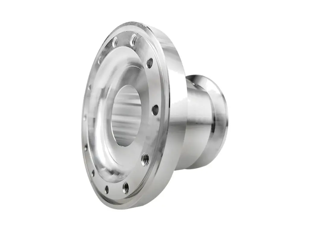
Flanged hubs turned from 6061-T6 bar, with a pilot bore held to H7 and 0.015 mm roundness, a flange face square to the bore within 0.02 mm, a spigot held to h8 concentric within 0.02 mm and a bolt circle positioned to ±0.05 mm. Hubs are balanced to G6.3 at 2,500 rpm before anodizing.
- Pilot Bore to H7
- Flange Face Square 0.02 mm
- Bolt Circle ±0.05 mm
- Hub Balanced at Speed
*Send the mating part drawing, not just the hub. The pilot diameter, the spigot and the bolt circle are all set by what mounts on the flange, and a hub made to its own drawing will not centre it.
Flanged Hub Overview
A flanged hub centres a rotating part on a shaft and clamps it against a face. The pilot bore sets the shaft fit, the spigot centres the mounted part and the flange face sets its axial position. All three have to come from one turning operation.
The hub is turned complete: bore, spigot, flange face and outside diameter, then the bolt circle is drilled from the bore centre. The part is balanced after drilling, corrected on the inside of the flange, and the pilot bore is protected before anodizing.
6061-T6 Aluminium Bar
6061-T6 is used for hubs on aluminium wheels and couplings because it is light, machines to a true bore and anodizes to a hard surface. Low inertia matters on a hub that starts and stops with the driven part.
7075-T6 or Steel
7075-T6 is chosen where the bolt circle carries a high torque and the flange must not deflect. Steel is specified for hubs that are pressed onto a shaft with a heavy interference fit, where aluminium would yield at the bore.
Aluminium is right where the hub is bolted to the driven part; steel where the hub is the interference fit and carries the whole torque through the bore.
Flanged Hub Specifications
Turning data for flanged hubs, with the bore, spigot and bolt values that decide whether the mounted part runs true.
| Specification | Machining Data | Specification | Machining Data |
|---|---|---|---|
| Product | Flanged Hub / Pilot Hub | Machining Process | CNC Turning, Boring, Drilling, Balancing |
| Material | 6061-T6 Aluminium Bar | Flange Diameter | Ø 80 – 380 mm |
| Pilot Bore | Ø 25 – 200 mm, H7, Roundness 0.015 mm | Flange Face | Square 0.02 mm, Flatness 0.02 mm |
| Bolt Circle | 4 – 12 Holes, Position ±0.05 mm | Hub Length | 30 – 200 mm |
| Spigot | Ø 40 – 250 mm, h8 | Concentricity | Spigot to Pilot Bore 0.02 mm |
| Surface Finish | Ra 1.6 µm Faces, Ra 0.8 µm Bore | Balance | G6.3 at 2,500 rpm |
| Customization | Keyway, Taper Bore, Set Screw Holes | Lead Time | 5 – 7 Days Sample, 12 – 16 Days Batch |
| Inspection | Air Gauge Pilot Bore, CMM Bolt Circle, Runout Between Centres, Balance | Packing | Foam Cradle, Bore Plugged, Carton |
Key Features of Our Flanged Hubs
Bore, spigot and face from one set-up.
Pilot Bore and Face in One Operation
The bore and the flange face are turned without reclamping, so the face runs square to the bore within 0.02 mm and the mounted part does not wobble.
Spigot Concentric to 0.02 mm
The spigot is turned from the same centre as the bore, which centres the mounted part on the hub rather than on the bolts.
Bolt Circle Drilled From the Bore
Holes are positioned to ±0.05 mm from the bore centre, so the bolts go in without opening the holes and the joint is not preloaded sideways.
Balanced After Drilling
Drilling the bolt circle removes material unevenly, so the hub is balanced afterwards and corrected on the inside of the flange.
Hub that has to centre a rotating part?
Surface Finishes for Flanged Hubs
The bore, spigot and flange face are fits; the rest of the hub is visible and needs corrosion protection only.
| Finish | Main Purpose | Finish | Main Purpose |
|---|---|---|---|
| Type II Anodizing | Corrosion protection and colour on the flange | Hard Anodizing | Wear resistance on the pilot spigot |
| Masked Pilot Bore | Keeps the bore at H7 after coating | Bead Blasting | Even matte before dye |
| Laser Marking | Bolt pattern and balance position | Bare Flange Face | Keeps the mounting face flat and conductive |
*Anodizing adds 5 to 10 µm and changes a H7 bore and an h8 spigot. Both are masked, and the flange face is left bare so the mounting plane stays flat.
Put your CNC milling parts into production today
All information and uploads are secure and confidential.
Trusted for Precision CNC Machined Components
Supporting OEM projects with accurate machining, flexible production, and reliable component quality.
Trusted for Precision CNC Milling.
Turning Process for Flanged Hubs
The pilot bore and the flange face are turned in one operation, so a wheel or a coupling mounted on the hub runs true without a shim.
01. Mating Part Review
Check the shaft size, the mating part pilot and the bolt pattern, and confirm which faces must stay bare before turning.
02. Turn Bore and Face
Turn the pilot bore, the spigot and the flange face in one operation, checking the bore with an air gauge before the part leaves the chuck.
03. Drill the Bolt Circle
Drill and counterbore the bolt circle from the bore centre, then deburr both faces of every hole before balancing.
04. Balance the Hub
Balance the hub to G6.3 at 2,500 rpm, correcting on the inside of the flange so the mounting face and the spigot are untouched.
05. Mask, Anodize, Check
Mask the bore, spigot and flange face, anodize, then check runout between centres and record the balance before packing.
Send the mating part and shaft drawings, and we will quote a hub with the bore, spigot and face turned in one operation.
Flanged Hub FAQs
0.02 mm, because both are turned from the same centre without reclamping. That is what centres the mounted part on the shaft rather than on the bolt clearance.
Because unbalance grows with the square of speed, and a hub that is fine at 500 rpm can shake a bearing at 2,500 rpm. Balancing is cheap compared with replacing a bearing.
Yes, a taper from 1:10 to 1:5 is turned and checked with a taper gauge, and the matching taper on the shaft is specified so the pair contacts over the full length.
By about 10 µm, which is enough to lose an H7 fit. The bore and spigot are masked, and the flange face is left bare so it stays flat.
It is drilled from the bore centre in the same set-up, positioned to ±0.05 mm. That is tighter than the clearance in a bolt hole, so the joint does not shift.
Yes, the keyway is cut after boring so it does not distort the bore, and the width is held to ±0.02 mm to suit the shaft key with a slip fit.
Other CNC Machined Mechanical Components
Explore additional precision CNC machined components manufactured for OEM applications and customized production needs.
CNC machined aluminium joint bracket and clamping blocks with a split bore, matched hinge pin and anodized finish for robot.
CNC milled aluminium split clamping blocks with a sawn split, matched halves and bores held to H7 for linear shafts.
Custom five-axis CNC machined stainless steel turbine stators and nozzle rings.
Precision CNC machined stainless steel gripper fingers for robot end effectors.
Custom CNC machined aluminum hollow L brackets with lightening cut-outs, machined in 6061-T6 or 7075-T6, flat to 0.05 mm and anodized to your colour.
Get high‑quality machined parts in as fast as 4 days with our expanded automated CNC milling!