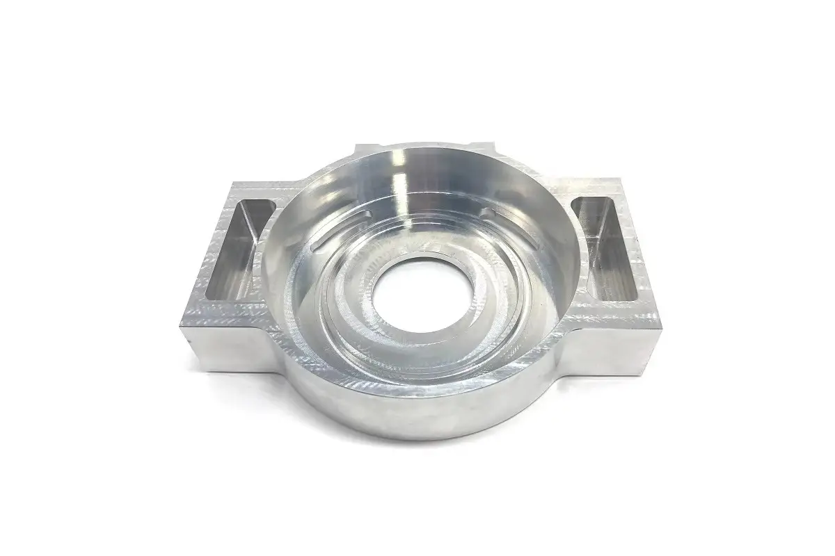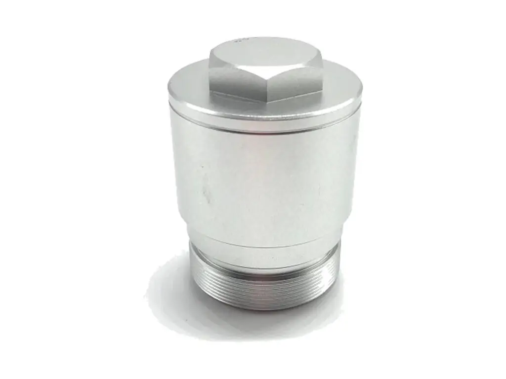


CNC Turned Aluminum Bearing Sleeve
Bearing sleeves turned from 6061-T6 and ground on the outside to h6, with a H7 bore concentric to 0.01 mm, a 5 mm wall, a shoulder square to 0.02 mm and faces parallel to 0.01 mm. Fits are masked so coating never touches them.
- OD Ground to h6
- Bore to H7, Wall 5 mm
- Concentricity 0.01 mm
- Shoulder Square 0.02 mm
*Send the bearing drawing with its tolerance class, not just the nominal bore. A sleeve turned to nominal for a P5 bearing leaves the wrong interference and the bearing will spin on the sleeve.
Bearing Sleeve Overview
A sleeve between a bearing and a housing has to hold two fits at once: the outside presses into the housing and the inside carries the bearing. If the two are not concentric, the shaft runs out by the difference.
The sleeve is turned with 0.3 mm left on the outside, bored and faced, then ground between centres so the OD and the bore share one axis before the shoulder is finished.
6061-T6 Aluminium Bar
6061-T6 is used for bearing sleeves in aluminium housings because the thermal expansion matches and the sleeve does not loosen when the housing warms up. It grinds to a clean h6 without loading the wheel.
6082-T6 or 2024-T351
6082 is used where the sleeve is also a structural spacer, and 2024 where the sleeve carries a needle bearing and the surface has to resist brinelling under a heavy radial load.
For a preloaded bearing pair the two sleeves in a set are matched in length to 0.01 mm and in weight to 2 g, otherwise the preload is uneven and one bearing runs hot.
Bearing Sleeve Specifications
Turning and grinding data for bearing sleeves, with the fit, concentricity and squareness values that decide whether the shaft runs true.
| Specification | Machining Data | Specification | Machining Data |
|---|---|---|---|
| Product | Bearing Sleeve / Bearing Spacer | Machining Process | CNC Turning, Boring, Cylindrical Grinding |
| Material | 6061-T6 Aluminium Bar | Envelope | OD 20 – 120 mm, Length 15 – 150 mm |
| Outside Diameter | h6, Roundness 0.005 mm | Bore | H7, Roundness 0.008 mm |
| Concentricity | 0.01 mm Between OD and Bore | Wall Thickness | 4 – 12 mm, ±0.05 mm |
| Shoulder Squareness | 0.02 mm | Face Parallelism | 0.01 mm |
| Surface Finish | Ra 0.4 µm OD, Ra 0.8 µm Bore | Chamfer | 0.5 × 30° Both Ends |
| Hardness | Brinell 95 Typical | Weight | Matched Within 2 g in a Set |
| Customization | Oil Grooves, Cross Holes, Flange, Keyway, Anodizing | Lead Time | 4 – 6 Days Sample, 10 – 14 Days Batch |
| Inspection | Micrometer OD, Air Gauge Bore, Roundness, Concentricity on Pins | Packing | Bore Plug, Foam Sleeve, Boxed |
Key Features of Our Bearing Sleeves
Ground outside, bored from the same axis, fits masked.
Outside Ground to h6
The OD is ground after turning, which holds roundness to 0.005 mm and lets the sleeve press in at the interference you specified instead of at the tool mark depth.
Bore and OD Share One Axis
Both are finished between centres, so concentricity stays within 0.01 mm and the shaft does not run out by the wall thickness variation.
Shoulder Square to 0.02 mm
The shoulder is faced after grinding, so a bearing seats flat and the preload goes through the race instead of through one edge.
Fits Masked Before Coating
The OD and bore are taped and plugged for anodizing, and both are re-gauged afterwards, so a coated sleeve still fits the bearing it was made for.
Sleeve that has to hold a bearing fit?
Surface Finishes for Bearing Sleeves
Both fits must stay bare, the exposed faces can be coated, and coating thickness must never reach the shoulder.
| Finish | Main Purpose | Finish | Main Purpose |
|---|---|---|---|
| Bare OD and Bore | Keeps the bearing fits unchanged | Clear Anodizing | Corrosion protection on non-fit faces |
| Masked Fits | Fits stay at h6 and H7 | Hard Anodizing | Wear resistance on a sliding sleeve |
| Bead Blasting | Even matte on exposed faces | Laser Marking | Sleeve size and set number |
| Anodizing Build | 10 – 15 µm, Non-Fit Faces | Assembly Oil | Light Film on the Bore |
| Fit Protection | Taped During Coating | Ultrasonic Clean | Before Bearing Fit |
| Set Matching | Weight Recorded per Sleeve | Protective Wrap | Per Sleeve |
*Anodizing on a h6 outside diameter would add 20 µm and turn an interference fit into a press that cracks the housing. Fits are masked and the sleeve is re-gauged after coating, every time.
Put your CNC milling parts into production today
All information and uploads are secure and confidential.
Trusted for Precision CNC Machined Components
Supporting OEM projects with accurate machining, flexible production, and reliable component quality.
Trusted for Precision CNC Milling.
Machining Process for Bearing Sleeves
The outside diameter is ground after turning, so the sleeve presses into the housing at the fit you specified instead of at whatever the tool left.
01. Bearing and Housing Review
Check the bearing tolerance class, the housing bore and the preload, then set the OD and bore limits from those, not from nominal.
02. Turn Leaving Grinding Stock
Turn the OD leaving 0.3 mm, bore and face the ends, and cut the shoulder square in the same set-up.
03. Bore to H7
Bore and finish the inside to H7, checking roundness at both ends with an air gauge before the part goes to the grinder.
04. Grind the Outside
Grind between centres to h6, checking the OD at three points and the concentricity against the bore with a dial indicator.
05. Mask, Coat, Gauge
Mask the fits, anodize if specified, then re-gauge the OD and bore and record the readings on the set tag.
Send the bearing class and the housing bore, and we will quote a sleeve ground to the interference your bearing needs.
Bearing Sleeve FAQs
A turned OD holds about 0.02 mm roundness and leaves a spiral tool mark that reduces the effective interference. Grinding holds 0.005 mm and gives a surface the housing actually grips.
For an aluminium housing and a 6205 bearing, 0.01 to 0.03 mm on the OD and a light push fit on the bore. Too much interference closes the bearing clearance and the bearing runs hot.
Yes, length within 0.01 mm and weight within 2 g across a set, which matters when two sleeves set the preload on a bearing pair.
It would, by 10 to 15 µm per surface. Fits are masked and the sleeve is re-gauged after coating, so the bearing still goes on with the specified interference.
0.01 mm, finished between centres. That is the number that shows up as shaft runout, and it is the reason the sleeve is not turned in one chuck and finished in another.
Yes, helical or circumferential grooves are cut before grinding, 0.5 mm deep, with the edges broken so they do not scrape the bearing seat.
Other CNC Machined Mechanical Components
Explore additional precision CNC machined components manufactured for OEM applications and customized production needs.
Custom CNC machined aluminum motor housings with bored bearing seats, cooling fins and mounting flanges.
Custom CNC machined aluminum hollow sleeve connectors for robot arm segments and linear modules.
Custom CNC machined aluminium brake booster check valve bodies for motorcycles and automotive systems.
Custom CNC machined aluminium mounting brackets for robots, automation and equipment mounting.
Explore CNC milled vacuum chambers with precision sealing faces, complex ports, internal cavities, and aluminum or 304L stainless.
Get high‑quality machined parts in as fast as 4 days with our expanded automated CNC milling!