

Home / CNC-Machining / CNC Milling / CNC Milled Steel Hydraulic Manifold Block
CNC milled 4140 steel hydraulic manifold block with cross-drilled galleries and G1/4 ports

CNC Milled Steel Hydraulic Manifold Block

Hydraulic manifold blocks milled from 4140 pre-hardened steel: 120 × 70 × 40 mm, six working G1/4 ports, two gauge ports and Ø6 cross-drilled galleries positioned to ±0.05 mm with an 8 mm minimum wall between passages. The mounting face is flat to 0.02 mm and every block is pressure tested at 350 bar for ten minutes before it is packed.

*Send the hydraulic schematic with the block drawing. We set the gallery depths and plug positions from the circuit, and a gallery drilled 3 mm too deep can break into the next passage.

Steel Hydraulic Manifold Overview

A manifold replaces a bundle of hoses with drilled passages inside one block. The passages have to meet exactly where the schematic says, the walls between them have to stay thick enough for the working pressure, and the port threads have to be square to the face so the fittings seal on the first turn.

The block is squared and the port faces are milled first, because every gallery is drilled from a port face. Galleries are drilled in stages with peck cycles, deburred through the ports, and inspected with a bore scope before the threads are cut. The finished block is plugged, pressure tested and marked with the port map.

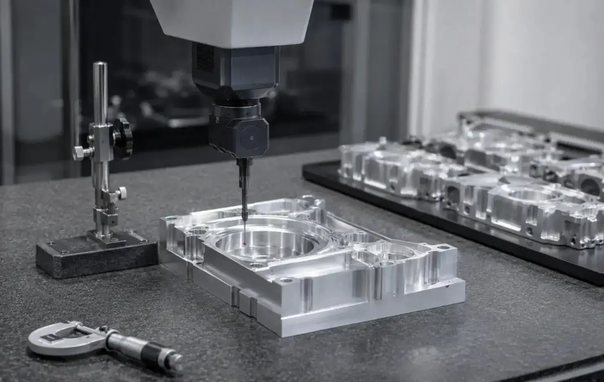
CMM inspection of a gripper jaw set, a brass manifold block and an eight-lobe flange plate
304L stainless steel round bar stock for CNC machining

4140 Pre-Hardened Steel

4140 at 28 HRC gives a manifold that will not creep at 350 bar and still machines cleanly enough to hold a G1/4 thread without tearing.

304L stainless steel plate and block stock for CNC machining

316L Stainless or 6082 Aluminium

316L is used for water-glycol and marine circuits, while 6082-T6 aluminium is chosen for mobile manifolds where the 1.9 kg steel block is too heavy for the valve stack.

A gallery wall under 6 mm will bulge under pressure cycling; the drawing is laid out with 8 mm as the minimum, and the bore scope confirms it.

Hydraulic Manifold Specifications

Drilling, threading and test data for blocks that carry pressure, not just fluid.

SpecificationMachining DataSpecificationMachining Data
ProductHydraulic Manifold BlockProcessCNC Milling, Cross Drilling, Tapping
Material4140 Pre-Hardened Steel, 28 HRCEnvelope120 × 70 × 40 mm
GalleriesØ6 ±0.05 mm, Depth 110 mmPort ThreadsG1/4, 6H, 12 mm Deep
Port Count6 Working, 2 GaugeMounting FaceFlatness 0.02 mm, Ra 1.6
Cross Hole Angle90°, Position ±0.10 mmPlug ThreadsG1/8, 6H
Wall Between Galleries8 mm MinimumEdge Break0.5 mm × 45°
Pressure Test350 bar, 10 min, No LeakWeightApprox. 1.9 kg
InspectionCMM, Bore Scope, Pressure RigBatch Size5 to 500 Pieces
FinishBlack Oxide or Zinc-NickelDrawing FormatSTEP, PDF, Hydraulic Schematic

Passages That Meet Where the Schematic Says

Faced ports, staged drilling, scoped galleries and a pressure test on every block.

All Galleries Drilled From Machined Faces

Each port face is milled flat before drilling, so the drill does not walk on a scaly surface and the gallery stays within 0.05 mm of its schematic position over a 110 mm depth.

Staged Peck Drilling

Deep galleries are drilled in 3 × diameter pecks with full coolant, which clears chips and keeps the hole straight instead of drifting at the bottom of a 110 mm run.

Bore Scope Before Threading

Every gallery is inspected with a 2 mm bore scope to confirm the cross hole is open and no burr is left at the intersection, before the port threads are cut.

Pressure Tested, Not Sampled

Each block is plugged, filled and held at 350 bar for ten minutes with the test recorded against the serial number, so a leaking block never reaches a customer.

Manifold that has to hold pressure?

Surface Finishes for Manifold Blocks

The outside protects against corrosion; the galleries and threads stay bare and clean.

FinishMain PurposeFinishMain Purpose
Black OxideOil-retaining corrosion protectionZinc-Nickel PlatingSalt spray above 500 hours
Electroless NickelWear and chemical resistance in galleriesPhosphatePaint adhesion base
Masked PortsThreads kept bare for fittingsPlug FittingGallery ends sealed before test
Laser MarkingPort identification on the block faceDeburr OnlyInternal use, no external coating
PassivationStainless 316 variantsPressure TestEvery block before packing
Gallery FlushLoose particle removal after platingPort CapsFittings protected in transit

*Plating inside a Ø6 gallery closes the passage and can flake under pressure; galleries and threads are masked before any coating is applied.

logo

Put your CNC milling parts into production today

All information and uploads are secure and confidential.

Trusted for Precision CNC Machined Components

Supporting OEM projects with accurate machining, flexible production, and reliable component quality.

Mechanical Equipment Customer
Every gallery met its cross hole on the first block, so nothing had to be re-drilled.

Industrial Components Buyer
The pressure test record shipped with the block, which our quality file requires.

Equipment Manufacturer
The G1/4 threads took the fittings square and sealed at the first attempt.

OEM Customer
OEM Customer
Two hundred hours at 300 bar and there is no weep at the gallery plugs.

Automation Industry Customer
The customized machining solution provided the dimensional accuracy required for our rotating equipment components.

Trusted for Precision CNC Milling.

How We Machine a Manifold Block

Every gallery is drilled from a faced surface and then scoped, so a cross hole that misses by half a millimetre never reaches the test rig.

01. Schematic and Wall Check

Lay the hydraulic schematic over the block drawing, confirm every gallery depth and check the wall thickness at each intersection before the first cut.

02. Square and Mill Port Faces

Face all six sides and mill every port face flat, marking the datum corner and the port map on the top face with a paint pen.

03. Drill Galleries in Stages

Drill each gallery from its port face in peck cycles, alternating drill sizes where a gallery steps down, and clear chips with high-pressure coolant.

04. Deburr and Scope

Deburr every intersection through the ports with a back-chamfer tool, then scope each gallery and photograph the run before threading.

05. Thread, Plug, Test and Finish

Cut the G1/4 and G1/8 threads, plug the gallery ends, pressure test at 350 bar, then black oxide or zinc-nickel with the ports masked.

Send the block drawing with the hydraulic schematic, and we will quote a manifold with the galleries drilled to your circuit and every block pressure tested.

Hydraulic Manifold Block FAQs

Up to 20 × diameter, so 120 mm, with a peck cycle and through-coolant. Beyond that the drill starts to drift and we would rather mill a pocket than drill a curved hole.

Yes. G1/4, G3/8, M14 × 1.5, 9/16-18 UNF and NPT are all cut with the appropriate tap or thread mill, and the thread depth is set from the fitting drawing.

We can fit the plugs we use for testing and leave them in place, or supply the block bare with the plugs in a bag, whichever suits your assembly line.

350 bar for ten minutes as standard, and up to 500 bar on request for steel blocks with a thicker wall. The test record ships with the block.

Yes, in 6082-T6 or 7075-T6 for mobile circuits. The gallery layout stays the same but the wall is increased to 10 mm because aluminium is less forgiving at intersections.

The block is ultrasonically cleaned after threading, blown through each port, and scoped again. The pressure test also flushes any loose particle out through the gauge port.

Other CNC Machined Mechanical Components

Explore additional precision CNC machined components manufactured for OEM applications and customized production needs.

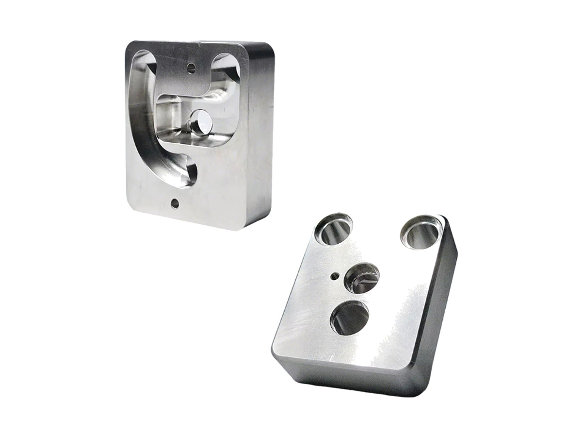
CNC machined C36000 brass manifold blocks with six bores in line within 0.03 mm, a 25 mm pitch, deburred cross ports and a 0.6.

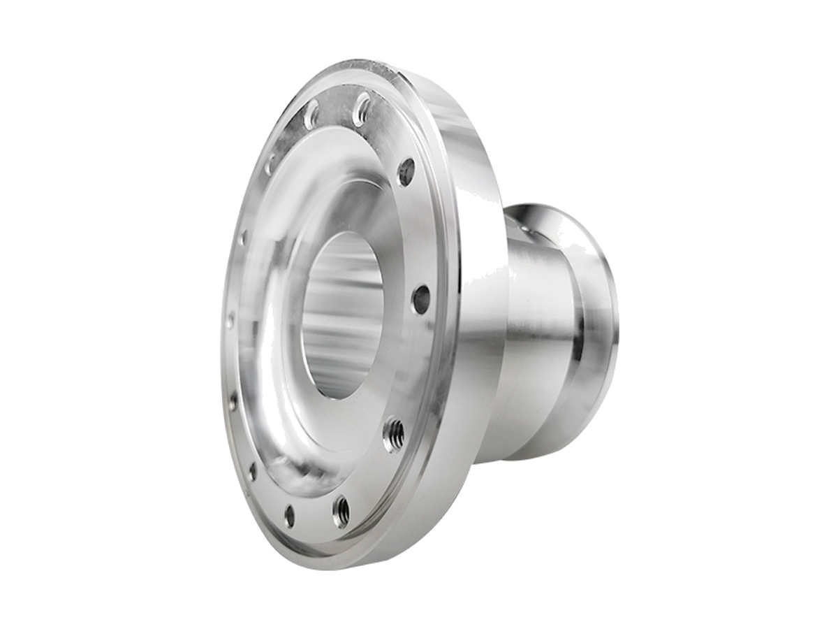
CNC turned 6061-T6 aluminium flanged hubs with a ground pilot bore, a faced flange and a dowelled bolt circle, held to 0.02 mm.

CNC turned 316L stainless steel stepped shafts with ground bearing journals, threaded ends and a keyway, held to 0.005 mm.

CNC machined 6061-T6 aluminium four-hole mounting blocks with a ground-flat base, two bored bores in line and a four-hole fixing.

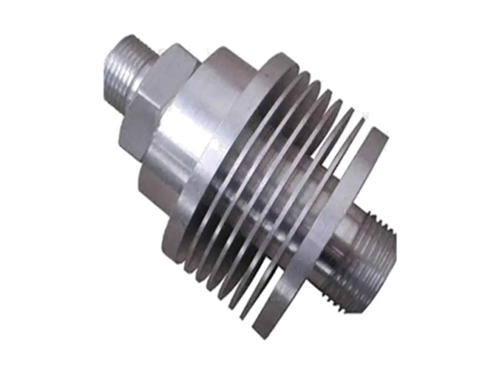
CNC turned 6061-T6 aluminium heat sink shafts with machined fins, threaded ends and a ground journal, combining heat dissipation.

Get high‑quality machined parts in as fast as 4 days with our expanded automated CNC milling!

Scroll to Top