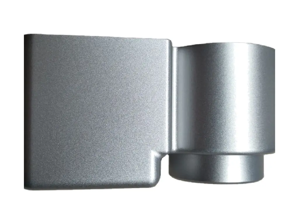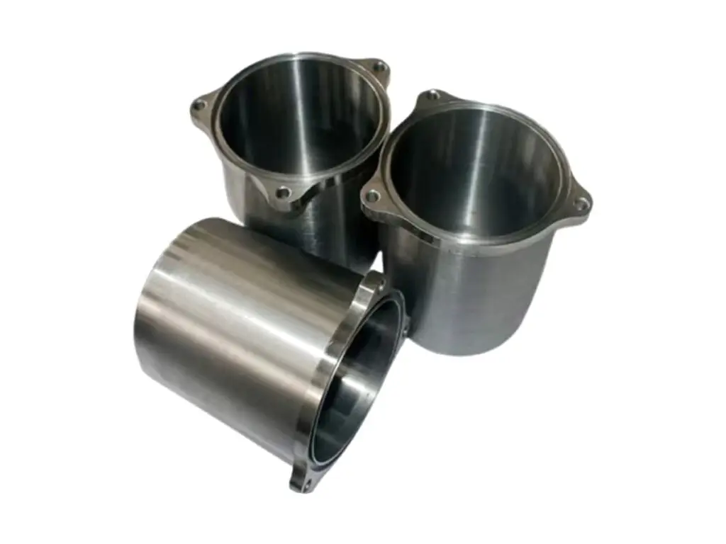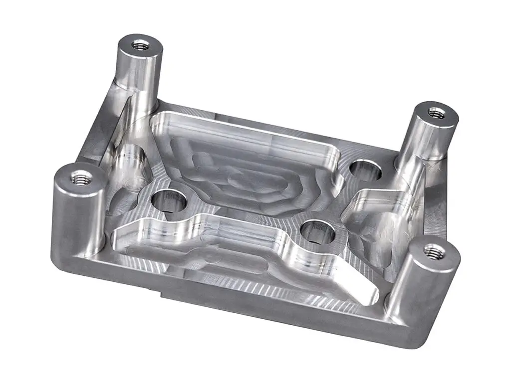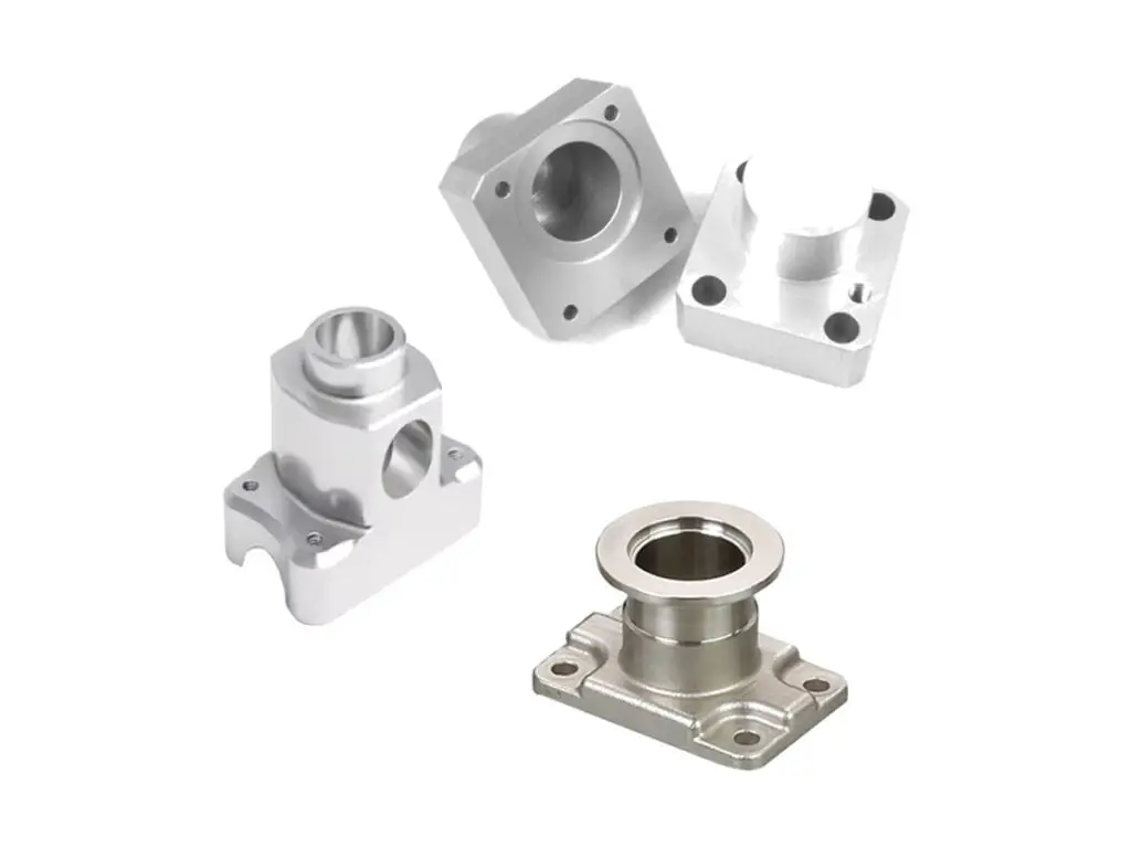
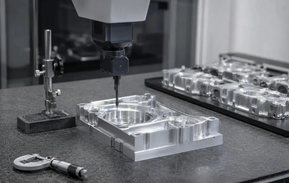


CNC Machined Aluminum Sensor Mount Set
Sensor mount sets machined from 6061-T6, with the sensor slot held to +0.05/0 mm and square within 0.02 mm, mounting faces square to the slot within 0.03 mm, dowel holes at ±0.01 mm and set faces matched within 0.05 mm.
- Slot at ±0.02 mm
- Dowel Holes at ±0.01 mm
- Set Faces Matched to 0.05 mm
- Clearance for the Sensing Gap
*Send the sensor body size and the sensing distance. The slot depth sets the gap, and a mount 0.2 mm shallow puts the sensor outside its switching range at the far end of travel.
Aluminium Sensor Mount Set Overview
A sensor mount is a small part with two jobs: hold the sensor square to the target and keep the gap constant when the machine vibrates. Both come down to how the slot and the mounting face relate.
The set is cut from one billet, the slot is milled and side finished, the mounting face is fly cut in the same clamping, and the dowel holes are reamed with the set pinned together so the pieces locate off the same pins.
6061-T6 Aluminium
6061-T6 is light enough not to load a moving axis and stiff enough at a 3 mm wall to keep the gap stable. It also anodizes evenly, which matters when several mounts sit side by side on a machine.
6082-T6 or 316 Stainless
6082-T6 is used for welded brackets, and 316 stainless where the mount sits in coolant mist or washdown and the aluminium would corrode at the slot edge.
A wall under 3 mm at the slot lets the mount flex when the sensor cable is pulled, and the gap moves by more than the sensor hysteresis.
Sensor Mount Set Specifications
Slotting and dowel data for sensor mounts, with the values that decide whether the gap stays where it was set.
| Specification | Machining Data | Specification | Machining Data |
|---|---|---|---|
| Product | Sensor Mount Set (3 – 5 Pieces) | Machining Process | 3-Axis CNC Milling, Slotting, Facing |
| Material | 6061-T6 Aluminium | Envelope | 30 × 25 mm to 80 × 60 mm per Piece |
| Sensor Slot | Width +0.05 / 0 mm, Square 0.02 mm | Slot Depth | ±0.05 mm |
| Mounting Face | Square to the Slot Within 0.03 mm | Flatness | 0.02 mm |
| Dowel Holes | Ø 4 H7, ±0.01 mm | Fixing Holes | M4 / M5, Position ±0.05 mm |
| Wall at the Slot | 3 mm Minimum | Sensing Gap | Set to ±0.10 mm on Assembly |
| Weight | 25 – 90 g per Piece | Coating Build | 15 – 20 µm Anodizing |
| Customization | Slot Size, Cable Exit, Set Quantity, Marking | Lead Time | 5 – 7 Days Sample, 12 – 16 Days Batch |
| Inspection | CMM Slot and Face, Pin Gauge on Dowels, Set Match Check | Packing | Numbered Bags, Foam Tray |
Key Features of Our Sensor Mounts
Slot side finished, face fly cut in the same clamping, set pinned together.
Slot Square to the Face
The slot and the mounting face are cut in one clamping, so the sensor axis stays perpendicular to the bracket face within 0.03 mm and the target distance does not change as the bracket is tightened.
Dowel Holes Reamed as a Set
The set is pinned and reamed together, so every mount registers on the same pin pattern and a replacement part locates without touching the machine frame.
Cable Exit Cut Before Coating
The cable exit and strain relief are milled before anodizing, so the coating does not bridge the exit and rub the cable jacket through on a moving axis.
Gap Marked on the Part
The sensing gap used at trial fit is laser marked on the mount, which is quicker than measuring on the machine when a sensor is replaced at shift change.
Mount that keeps the gap stable?
Finishes for Sensor Mounts
The slot is functional, the face is a datum, the outside is cosmetic.
| Finish | Main Purpose | Finish | Main Purpose |
|---|---|---|---|
| Clear Anodizing | Protection without changing the slot | Black Anodizing | Dark mounts on machine frames |
| Bead Blasting | Even matte across the set | Hard Anodizing | Wear face where the sensor slides |
| Masked Slot | Slot stays at gauge size | Chromate Conversion | Conductive mount for earthing |
| Laser Marking | Position number and sensing gap | Edge Break | 0.3 mm, No Burr in the Slot |
| Set Trial Fit | Sensors checked in the mounts | Face Film | Protection on the mounting face |
| Salt Spray | 480 h on 6061 | Slot Recheck | Width After Coating |
*Anodizing closes a 0.05 mm slot by 0.04 mm on width; slots under 6 mm are masked, otherwise the sensor body will not slide in after coating.
Put your CNC milling parts into production today
All information and uploads are secure and confidential.
Trusted for Precision CNC Machined Components
Supporting OEM projects with accurate machining, flexible production, and reliable component quality.
Trusted for Precision CNC Milling.
Making a Sensor Mount Set
Every mount in the set is slotted from the same datum, so a sensor swapped from one station to the next sits at the same gap without re-teaching.
01. Sensor and Gap Review
Check the sensor body, cable exit and switching distance, then set the slot depth so the gap lands in the middle of the sensing range.
02. Cut and Square the Set
Cut all pieces from one billet, face to a common thickness within 0.02 mm and number each piece on the back.
03. Slot and Face
Mill the slot, side finish both walls, then fly cut the mounting face in the same clamping so the two features stay related.
04. Ream Dowels and Trial Fit
Pin the set together, ream the dowel holes through the aligned pieces, fit the sensors and check the gap on a height gauge.
05. Anodize and Mark
Mask the slots, anodize, laser mark the gap and position, and pack the pieces in order with their pins.
Send the sensor drawing and the mounting layout, and we will quote a numbered set slotted from one datum with the gap marked on each piece.
Sensor Mount Set FAQs
We set the slot depth so the gap lands in the middle of the switching range, then mark the achieved gap on the part. The final gap is set on the machine with a feeler gauge.
Three to five is typical, all from one billet and pinned together for reaming. Larger sets are split, because a 300 mm billet moves too much between roughing and finishing.
A round sensor needs a bored seat rather than a slot, or a slot with a V-groove cut in the base. We cut whichever matches the sensor body you are using.
The cable exit is milled to clear the gland and the bend radius, which is why we ask for the sensor drawing rather than just the body diameter.
About 20 µm per wall, so a slot at the top of tolerance is masked before coating. Unmasked slots under 6 mm often need reaming after anodizing.
Yes, from the set number. The replacement locates on the same dowels, though its face may sit 0.02 mm off the original, which is inside the sensor tolerance.
Other CNC Machined Mechanical Components
Explore additional precision CNC machined components manufactured for OEM applications and customized production needs.
Five-axis CNC machined 6082-T6 aluminium manifold plates with cross-drilled galleries, spotfaced port faces and ports on five.
CNC machined 7075-T6 aluminium fork slider legs with a honed bore, machined axle slots and brake caliper lugs, held to ±0.03 mm.
CNC machined 316L stainless hinge blocks with twin knuckle bores, a square mounting face and a matched pin bore, holding knuckle.
CNC turned 316L stainless cylinder cups with a thin uniform wall, a flat closed end and a bore to H8, machined from solid bar and.
CNC machined 6061-T6 aluminium servo actuator housings with a bored bearing register, ribbed walls and a machined gasket face,.
Get high‑quality machined parts in as fast as 4 days with our expanded automated CNC milling!