
Quick Answer
Thin-wall aluminum CNC machining is used when drone and robotics parts need lightweight structure, accurate assembly, deformation control, stable surface finish, and reliable inspection after machining.
Key Takeaways
- Thin-wall parts are not just “lighter parts”; they require careful control of stress, fixturing, toolpath, wall thickness, and inspection.
- Machining 6061 T6 aluminum is often suitable for lightweight housings, brackets, covers, and support structures.
- For higher strength-to-weight requirements, 7075 aluminum may be considered, but cost, machinability, and surface treatment should be reviewed.
- Drone and robotics buyers care about weight, stiffness, vibration, flatness, hole position, and repeatable assembly.
- Good thin-wall machining depends on DFM review before production, not only final inspection after machining.
- SinoRise can support thin-wall aluminum parts through CNC milling, 5-axis machining, surface finishing, inspection, and small-to-medium batch production.
Abstract
Drone and robotics parts often need to be light, compact, accurate, and strong enough for real working conditions. A thin-wall aluminum housing may reduce payload weight, but it can deform during clamping. A robotic bracket may look simple, but if flatness or hole position shifts, the assembly may lose repeatability. A UAV frame part may pass visual inspection but fail when vibration, coating thickness, or screw preload is added.
This article explains thin-wall aluminum CNC machining from an engineering and sourcing perspective. It focuses on deformation control, lightweight design, material selection, machining strategy, surface finishing, inspection methods, and common risks for drone and robotics components. The goal is to help buyers ask better RFQ questions and source more reliable aluminum CNC machining parts.
What Thin-Wall Aluminum CNC Machining Means for Drone and Robotics Parts?
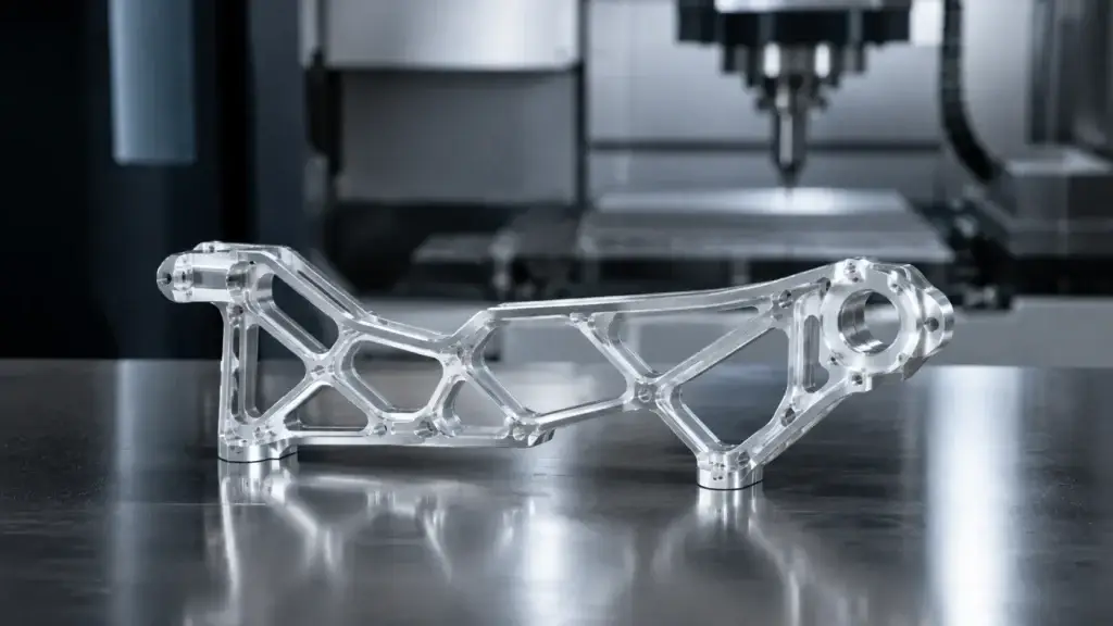
Thin-wall aluminum CNC machining refers to producing parts with relatively thin structural walls, pockets, ribs, shells, or lightweight sections while maintaining functional tolerances. These parts are common in drones, UAV systems, robotic arms, end-effectors, sensor housings, camera mounts, battery enclosures, and compact automation modules.
For drone projects, weight is not a secondary issue. Under FAA Part 107, a small unmanned aircraft is defined as an unmanned aircraft weighing less than 55 pounds at takeoff, including everything attached or onboard. This regulatory definition does not tell engineers how to design parts, but it shows why total aircraft weight matters in real UAV systems.
Why Thin Walls Are Difficult to Machine?
Thin-wall parts are difficult because material removal changes stiffness. A solid aluminum block is stable before machining, but as pockets, cavities, and ribs are cut away, the remaining walls can move under cutting force, clamp pressure, heat, and internal stress release.
Common challenges include:
- Wall vibration during milling
- Part deformation after unclamping
- Thin edge burrs
- Poor flatness on large pocketed surfaces
- Hole position shift after stress release
- Surface finish variation on flexible walls
- Coating thickness affecting final fit
Where Thin-Wall Parts Are Used?
Thin-wall aluminum parts are often used where weight and structure must be balanced:
| Application | Typical Thin-Wall Parts | Main Concern |
| Drones / UAVs | Frames, housings, camera mounts, battery covers | Weight, vibration, stiffness |
| Robotics | Arm links, joint covers, end-effector brackets | Repeatability, rigidity, fit |
| Vision systems | Sensor housings, lens brackets, optical mounts | Alignment and stability |
| Automation equipment | Lightweight fixtures, moving brackets, covers | Cycle speed and durability |
| Portable devices | Enclosures, heat-dissipation housings | Weight, appearance, assembly |
Why Machining 6061 T6 Aluminum Requires Deformation Control?
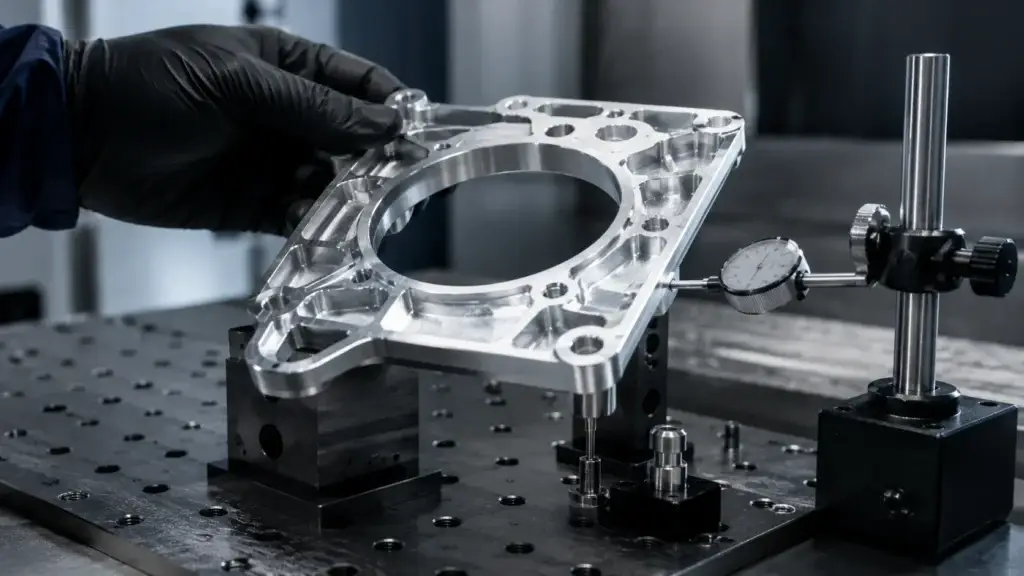
Machining 6061 T6 aluminum is common for thin-wall drone and robotics parts because it provides a practical balance of machinability, weight, corrosion resistance, cost, and anodizing compatibility. However, 6061-T6 still requires careful machining strategy when walls become thin.
The mistake is assuming aluminum is easy simply because it cuts faster than steel. For thin-wall structures, the issue is not only cutting speed. It is how the part behaves after most of the material has been removed.
6061-T6 vs 7075 Aluminum for Lightweight Parts
6061-T6 is often selected for housings, covers, frames, and brackets where machinability and surface treatment matter. 7075 aluminum is stronger and may be used for higher-load lightweight parts, but it usually requires closer review of cost, finishing, and corrosion protection.
Material Selection Table
| Material | Best For | Advantage | Watch Point |
| 6061-T6 aluminum | Drone housings, brackets, covers, robot supports | Good machinability and finish compatibility | Needs deformation control for thin walls |
| 7075 aluminum | High-strength lightweight frames or load-bearing brackets | Higher strength-to-weight ratio | Higher cost and more finish planning |
| 5052 aluminum | Sheet-like covers, formed structures | Good corrosion resistance | Less suitable for highly detailed CNC geometry |
| Titanium | Compact high-strength components | Strong and corrosion-resistant | Expensive and slower to machine |
| POM / PEEK | Lightweight non-metallic support parts | Low friction or insulation | Lower stiffness than metals |
For many RFQs, machining 6061 T6 aluminum is the practical starting point. The supplier can then advise whether the part needs 7075, local thickening, ribs, or a design change.
Common Thin-Wall Components in UAV Parts Machining
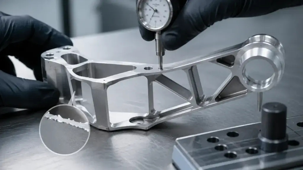
In UAV parts machining, thin-wall components are usually not decorative. They carry loads, hold electronics, align sensors, reduce weight, and protect internal assemblies.
Drone Housings, Frames, Covers, and Brackets
Common thin-wall UAV and drone parts include:
- Drone frame plates
- Camera gimbal brackets
- Sensor housings
- Motor mounting plates
- Battery compartment covers
- Lightweight heat-dissipation housings
- Antenna brackets
- Payload mounting parts
- Landing gear connectors
- Drone housing machining parts
- UAV fixture and test parts
Part Category Table
| Part Type | Key Machining Requirement | Typical Risk |
| Thin-wall housing | Flatness, bore fit, surface finish | Deformation after unclamping |
| Camera mount | Hole position, angular alignment | Vibration and image instability |
| Frame plate | Weight reduction, stiffness | Warping or weak corners |
| Sensor bracket | Datum accuracy, repeatable fit | Misalignment after assembly |
| Motor mount | Concentricity and bolt pattern | Vibration under load |
| End-effector bracket | Lightweight but stiff structure | Flex during operation |
Design Rules for Aluminum CNC Machining Parts
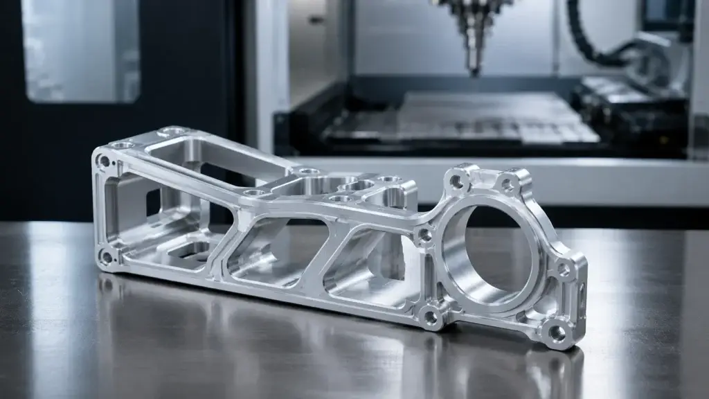
For aluminum CNC machining parts, design choices often decide machining success before the first tool touches the material. A supplier can improve toolpaths and fixturing, but an overly thin, unsupported wall may still deform.
Wall Thickness, Ribs, Radii, and Datum Planning
Good thin-wall design should include:
- Avoid extremely thin walls unless function requires them
- Add ribs instead of making all walls thicker
- Use generous internal radii where possible
- Avoid deep narrow pockets
- Keep screw bosses supported by surrounding material
- Define functional datums clearly
- Separate cosmetic surfaces from critical mounting surfaces
- Consider coating thickness before final tolerance is set
ASME describes Y14.5 as the authoritative guideline for the design language of GD&T, which matters when thin-wall parts require clear datums, true position, flatness, perpendicularity, and profile control.
Thin-Wall DFM Checklist
| DFM Question | Why It Matters |
| Which wall is function-critical? | Prevents over-tight tolerance everywhere |
| Can ribs replace full-thickness material? | Improves stiffness without excess weight |
| Are holes too close to thin edges? | Reduces cracking and distortion risk |
| Are datums stable after machining? | Improves inspection and assembly reliability |
| Will anodizing affect fit? | Prevents coating buildup problems |
| Can the part be held without distortion? | Reduces clamping-related deformation |
Process Strategy for High Precision CNC Machining
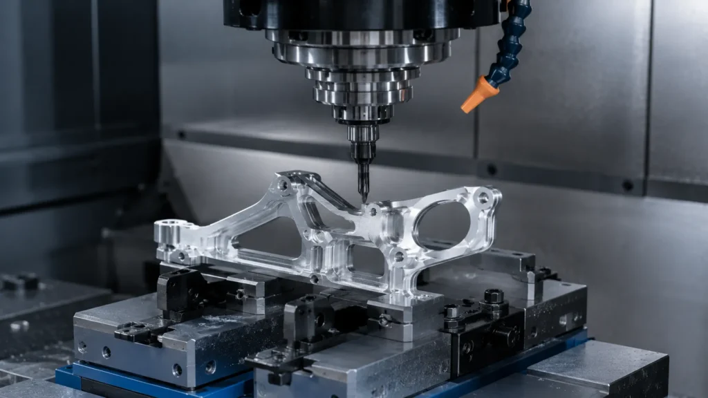
In high precision CNC machining, thin-wall parts should be machined with a process plan rather than a simple “cut to drawing” approach. The process should control stress, support, heat, and final inspection.
Fixturing, Roughing, Finishing, and Toolpath Control
A good process strategy may include:
- Rough machining while the part still has more material support
- Stress-relief consideration for high-risk parts
- Balanced material removal from both sides
- Soft or custom fixtures to reduce clamping marks
- Avoiding excessive cutting force on unsupported walls
- Leaving finishing allowance for final passes
- Using sharp tools and proper chip evacuation
- Controlling coolant and heat buildup
- Final finishing after key stress release
Recommended Machining Methods
| Method | Best For | Benefit |
| CNC milling | Housings, frames, brackets, covers | Flexible pocketing and contour machining |
| 5-axis machining | Complex thin-wall structures | Fewer setups and better access |
| Turning-milling | Cylindrical housings with side features | Reduces re-clamping error |
| Wire cutting | Thin flat profiles or precise slots | Good for accurate profiles |
| CMM-assisted inspection | Complex datum relationships | Confirms geometry after machining |
Surface Finishing for Drone Housing Machining and Robotics Parts
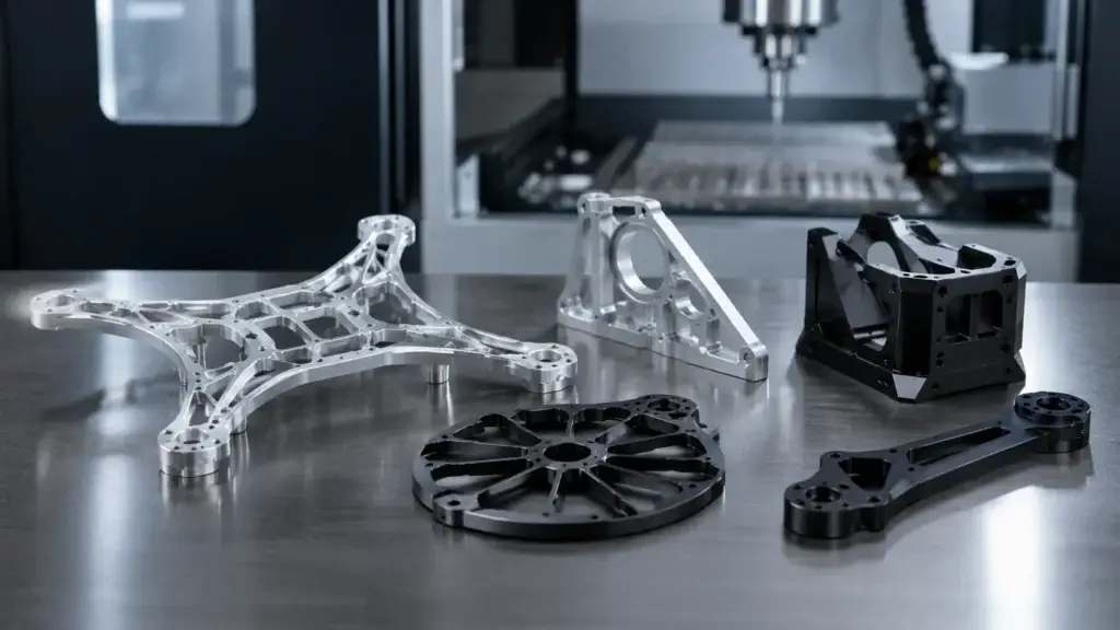
For drone housing machining and robotic aluminum parts, finishing is both functional and visual. It can protect the part, improve wear resistance, reduce reflection, or create a consistent appearance.
Anodizing, Hard Anodizing, Bead Blasting, and Masking
Common finishing options include:
| Finish | Best For | Risk to Review |
| Anodizing | Aluminum housings, covers, brackets | Coating buildup in holes and threads |
| Hard anodizing | Wear areas and repeated assembly parts | Thickness affects tight fits |
| Bead blasting + anodizing | Premium matte appearance | Can affect sharp edges or datums |
| Black anodizing | Optical, camera, and sensor-related parts | Gloss level and masking may matter |
| Chemical conversion coating | Conductive or electrical grounding areas | Finish specification must be clear |
| As-machined | Prototype and internal testing | Less corrosion and appearance control |
SinoRise’s surface treatment page lists integrated processes including sandblasting, anodizing, electroplating, and powder coating, with compatibility across aluminum, steel, stainless steel, copper, and titanium alloys.
Finish Planning Before Production
For thin-wall parts, finishing should be discussed before machining because coating can change:
- Thread fit
- Bore diameter
- Sliding fit
- Bearing seat clearance
- Edge feel
- Appearance consistency
- Electrical contact areas
Inspection Methods for Precision CNC Machined Components
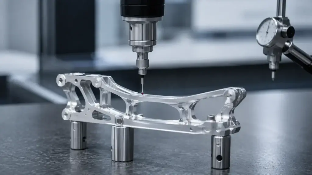
Thin-wall precision CNC machined components should be inspected after machining and after surface treatment when needed. Some deformation only becomes visible after the part is released from the fixture or after finishing.
What Should Be Inspected After Machining?
Important checks include:
- Wall thickness
- Flatness
- Hole position
- Bore diameter
- Parallelism
- Perpendicularity
- Profile tolerance
- Thread quality
- Burrs and edge condition
- Surface roughness
- Coating thickness
- Assembly fit with mating parts
Robotics applications also make repeatability important. ISO 9283 describes methods for specifying and testing industrial robot performance characteristics such as pose accuracy and pose repeatability, which shows why mechanical part consistency can matter in robot assemblies.
Thin-Wall Inspection Checklist
| Inspection Method | What It Checks |
| CMM inspection | Hole position, datum relationship, profile |
| Height gauge | Flatness-related checks and step height |
| Pin gauge | Hole and fit verification |
| Thread gauge | Thread accuracy after machining or coating |
| Micrometer / caliper | General size and wall thickness |
| Surface roughness tester | Functional and visible surfaces |
| Coating thickness gauge | Anodizing or plating impact |
| Assembly check | Real fit with screws, bearings, sensors, or covers |
Common Risks in Thin-Wall Robotic CNC Machining
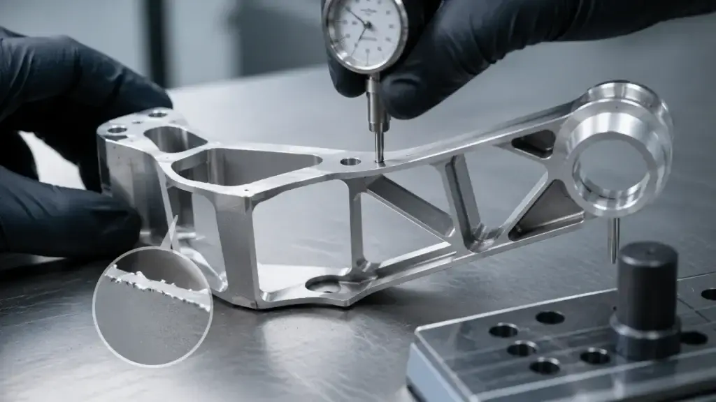
Thin-wall robotic CNC machining projects often fail because buyers focus only on weight reduction. But a part that is too light can lose stiffness, vibrate, deform, or fail assembly.
Deformation, Vibration, Burrs, and Coating Buildup
| Risk | What Happens | Prevention |
| Too-thin wall | Deformation during clamping or cutting | Add ribs or increase local thickness |
| Deep pocket | Tool deflection and chatter | Use larger radii and staged roughing |
| Weak screw boss | Thread failure or cracking | Add support around fastener areas |
| Poor datum planning | Inspection disagreement | Define stable functional datums |
| Coating buildup | Holes, threads, or bores too tight | Use masking or tolerance compensation |
| Burr on thin edge | Assembly interference or scratches | Add deburring requirement |
| Over-tight tolerance | Cost increases without functional gain | Tolerate only critical features tightly |
How to Reduce Sourcing Risk?
Before placing an order, buyers should send:
- 3D CAD file
- 2D drawing with critical dimensions
- Target wall thickness
- Material grade
- Surface finish
- Expected load or mounting condition
- Mating part information
- Inspection requirements
- Quantity and batch plan
- Whether prototype, first article, or small batch approval is needed
A clear RFQ helps the supplier quote the real work, not just the material and cycle time.
How SinoRise Supports Thin-Wall Aluminum CNC Machining?
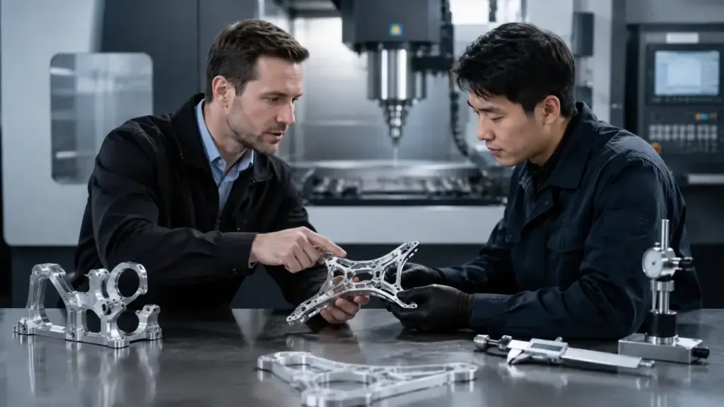
SinoRise supports custom CNC machining from prototype to production, including CNC milling, CNC turning, turning-milling, 5-axis machining, precision machining, and surface treatment. Its official website also highlights flexible small and medium-batch production, 35+ surface finishing options, 80+ metals and plastics, and precision capability up to ±0.005mm.
For thin-wall aluminum drone and robotics parts, SinoRise can support:
- Drawing and DFM review
- Thin-wall machining strategy review
- Machining 6061 T6 aluminum and other aluminum alloys
- CNC milling and 5-axis machining for lightweight structures
- Turning-milling for cylindrical housings with side features
- Anodizing, hard anodizing, bead blasting, and masking coordination
- CMM and dimensional inspection
- Prototype, first article, small-batch, and repeat production
- Support for UAV, robotics, optical, semiconductor, medical, and automotive applications
The practical value is not only producing a thin part. It is helping the buyer control deformation, finish, tolerance, and cost before the part enters production.
FAQ About Thin-Wall Aluminum CNC Machining
What Is Thin-Wall Aluminum CNC Machining?
Thin-wall aluminum CNC machining is the process of making lightweight aluminum parts with thin walls, pockets, ribs, shells, or reduced-weight structures while maintaining functional tolerances and assembly stability.
Is 6061-T6 Aluminum Good for Drone and Robotics Parts?
Yes. Machining 6061 T6 aluminum is common for drone housings, robotic brackets, covers, frames, and support parts because it balances machinability, weight, cost, corrosion resistance, and anodizing compatibility.
When Should I Use 7075 Aluminum Instead of 6061-T6?
Use 7075 aluminum when the part needs higher strength-to-weight performance. However, it usually requires closer review of machining cost, finishing, corrosion protection, and material availability.
Why Do Thin-Wall CNC Parts Deform?
Thin-wall parts deform because material removal reduces stiffness. Cutting force, clamping pressure, heat, internal stress release, poor toolpath strategy, and surface treatment can all contribute to deformation.
How Can I Reduce Deformation in Thin-Wall CNC Machining?
Use proper wall thickness, ribs, stable datums, balanced roughing, suitable fixtures, sharp tools, controlled finishing passes, and inspection after unclamping. DFM review before machining is strongly recommended.
What Surface Finish Is Best for Thin-Wall Aluminum Parts?
Anodizing is common for aluminum drone and robotics parts. Hard anodizing is useful for wear areas. Bead blasting plus anodizing creates a uniform matte appearance. Masking may be needed for holes, threads, bores, and datum faces.
What Should I Include in an RFQ for Thin-Wall Aluminum Parts?
Include 3D files, 2D drawings, material grade, target wall thickness, surface finish, tolerance requirements, critical features, application background, mating parts, inspection requirements, and expected quantity.
Conclusion
Thin-wall aluminum CNC machining is not a generic drone parts topic. It is a high-value machining challenge where lightweight design, deformation control, stiffness, tolerance, finishing, and inspection must be planned together.
For drone and robotics buyers, the goal is not simply to remove as much material as possible. The goal is to keep the part light while still protecting alignment, vibration resistance, assembly fit, and repeatability.
Machining 6061 T6 aluminum is often a practical starting point for thin-wall housings, brackets, covers, and support parts. But the final result depends on design rules, machining strategy, fixturing, surface treatment, and inspection. SinoRise supports thin-wall aluminum CNC machining by connecting engineering review, CNC machining, finishing, and quality control into one production-ready workflow.
References
[1] eCFR — 14 CFR Part 107 defines a small unmanned aircraft as weighing less than 55 pounds at takeoff, including everything onboard or attached.
[2] ASME — Y14.5 is described as the authoritative guideline for the design language of geometric dimensioning and tolerancing.
[3] ISO — ISO 9283 describes methods for specifying and testing industrial robot performance characteristics such as pose accuracy and pose repeatability.
[4] SinoRise — Official CNC machining website, listing prototype-to-production CNC machining, small and medium-batch production, materials, surface finishes, precision capability, and industry support.
[5] SinoRise — Surface Treatment page, listing integrated surface treatment options including sandblasting, anodizing, electroplating, powder coating, and material compatibility.