
A semiconductor fixture plate is more than a flat piece of machined aluminum. It may position a wafer carrier, support metrology equipment, align a robotic handling system, distribute vacuum or establish the mounting reference for an entire machine module.
For these applications, individual dimensions are only part of the requirement. A plate can meet its length, width and hole diameters while still failing during assembly because the mounting face is distorted, locating holes are shifted from the functional datums, or anodizing has changed a precision fit.
Reliable semiconductor fixture plate CNC machining therefore requires a connected plan covering material stability, datum strategy, staged material removal, hole position, surface treatment and final inspection.
This guide explains how these factors affect semiconductor tooling plates, wafer fixtures, vacuum chucks and precision equipment base plates.
Semiconductor Fixture Plate Requirements at a Glance
| Requirement | Why it matters | Main process control | Final verification |
| Flatness | Supports stable mounting or wafer contact | Material selection, balanced machining and low-distortion clamping | Surface plate, height measurement or CMM |
| Parallelism | Maintains the relationship between mounting planes | Datum control and planned face machining | CMM or height measurement |
| Coplanarity | Keeps separate pads at a common functional height | Same-reference finishing strategy | Multi-point CMM or height inspection |
| Hole position | Controls assembly and repeatable location | Datum-based programming and limited repositioning | CMM or functional gauge |
| Dowel-hole fit | Establishes accurate repeat positioning | Final hole sizing and finish compensation | Bore or plug gauge plus position inspection |
| Surface condition | Affects contact, sealing, cleaning and appearance | Controlled machining and finishing | Roughness and visual inspection |
| Treatment thickness | Changes holes, pads, threads and fits | Machining allowance and masking | Post-treatment dimensional inspection |
| Cleanliness | Protects wafers and sensitive assemblies | Deburring, cleaning and protected handling | Visual and project-specific verification |
The exact limits depend on plate size, thickness, application, installation method and operating environment. A flatness value should never be evaluated without these conditions.
What Is a Semiconductor Fixture Plate?
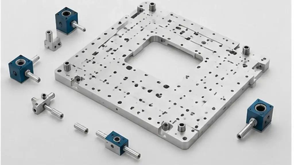
The term includes several types of machine parts for semiconductor manufacturing.
Alignment plates
Alignment plates establish the position of equipment modules, sensors, stages or robotic interfaces. Their dowel-hole patterns and datum surfaces often matter more than the outside profile.
Wafer handling fixtures
These fixtures support or locate wafers, carriers and process components. Contact pads may need controlled coplanarity, low burr risk and a defined surface condition.
Vacuum chucks and process plates
Vacuum grooves, ports and sealing lands must work together to provide stable holding. Flatness alone is not enough if grooves contain burrs or the sealing surface is damaged.
Metrology and calibration plates
These plates support inspection, optical or measurement assemblies. Their performance may depend on the relationship between a reference face, precision holes and mounting interfaces.
Equipment base plates
A semiconductor equipment base plate may support motion systems, optical components, gas systems or process modules. It may require both structural rigidity and precise alignment between widely separated features.
Each application requires a different balance of strength, dimensional stability, surface protection and inspection evidence.
Start With Functional Datums and CTQs
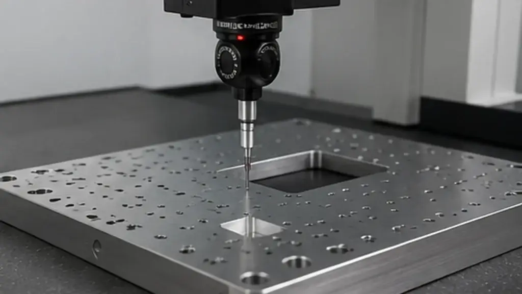
The machining plan should begin with the features that control the plate’s function.
Common critical-to-quality features include:
- Primary mounting face
- Secondary locating edge
- Dowel holes
- Precision bores
- Wafer support pads
- Optical or sensor mounting faces
- Vacuum sealing lands
- Threaded mounting interfaces
- Parallel equipment interface planes
A practical datum structure might use:
- Datum A: the primary mounting surface
- Datum B: a locating edge or secondary plane
- Datum C: a dowel hole or perpendicular feature
The exact structure should reflect how the plate is installed and used. Selecting convenient manufacturing surfaces that do not match the actual assembly can produce a part that measures correctly in isolation but does not align correctly in the machine.
Datum planning affects:
- Workholding
- Machining sequence
- Re-clamping strategy
- Hole programming
- CMM alignment
- Inspection reports
For semiconductor CNC precision machining, manufacturing and inspection should use the same functional reference logic wherever practical.
Choosing Aluminum for Semiconductor Fixture Plates
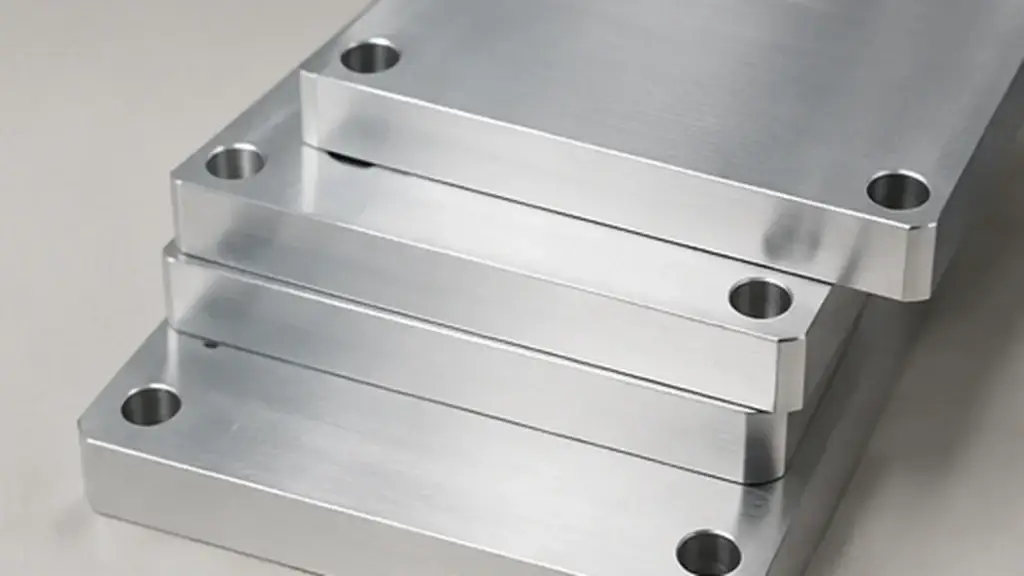
Aluminum is widely used because it combines low weight, good machinability, corrosion resistance and thermal conductivity. However, not every aluminum plate behaves the same during machining.
6061-T6 and 6061-T651
6061 is commonly evaluated when the plate requires:
- Structural strength
- Threaded features
- Good general machinability
- Welded or assembled structures
- Type II or Type III anodizing
- A balance of mechanical and finishing performance
T651 material has undergone stress-relief treatment, which can reduce dimensional movement compared with material in a less stable condition. It does not eliminate distortion when material removal is highly unbalanced.
Cast tooling plate
Cast tooling plate, including MIC-6 or equivalent grades, is often considered when dimensional stability and large-area machining are priorities.
It may be suitable for:
- Fixture plates
- Metrology bases
- Vacuum plates
- Large flat tooling
- Components with extensive pocketing
Its value is not simply that the raw plate is flat. A more uniform and stress-relieved internal condition may help reduce movement when both faces are machined.
However, cast tooling plate is not automatically the best option for every project. Mechanical strength, thread loading, surface-treatment appearance and material certification still need to be evaluated.
Select material by finished function
A useful comparison is:
| Project priority | Material direction to evaluate |
| Extensive machining and dimensional stability | Cast tooling plate |
| Higher strength and threaded interfaces | 6061-T6 or T651 |
| Uniform decorative anodizing | Suitable wrought aluminum alloy |
| Vacuum sealing or process surface | Material quality, surface finish and sealing requirements |
| High-wear local contact | Base material plus a suitable wear-resistant treatment |
Material selection should follow the final operating requirement, not only the raw stock certificate.
Why Large Fixture Plates Lose Flatness?
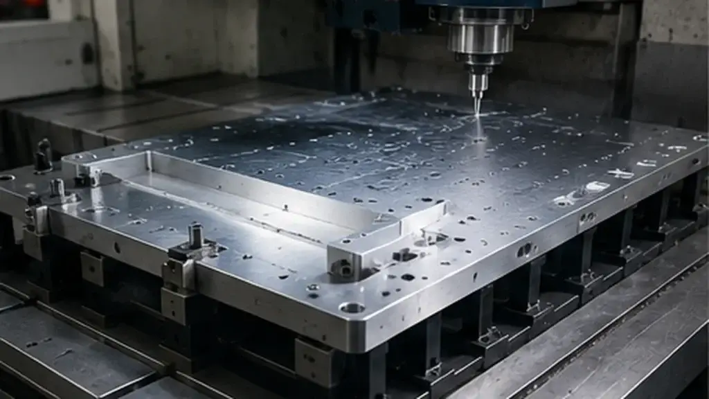
Large or thin plates can move during machining even when the raw material initially appears flat.
Residual stress
Rolling, heat treatment, straightening, sawing and prior processing can leave internal stress in the plate. Removing material changes the balance of that stress.
A plate may remain flat while clamped but bow after it is released.
Asymmetric material removal
Removing a large pocket from one side while leaving the opposite side nearly unchanged creates an unbalanced section.
The risk increases when the final geometry contains:
- Thin floors
- Deep pockets
- Large recessed areas
- Unequal wall thickness
- Dense holes on one side
- Interrupted ribs
Clamping distortion
Excessive clamping force can force a bowed plate against the fixture. The machined surface appears flat under restraint, then returns toward its original shape after unclamping.
Machining heat
Heat from cutting, spindle operation and coolant variation can temporarily change the plate shape. Precision finishing and inspection should not be performed while the part remains thermally unstable.
Surface treatment and handling
Cleaning, etching, anodizing, hanging and transportation may change the final geometry or expose existing instability.
This is why drawing requirements should state whether flatness applies before or after treatment.
How to Control Flatness During CNC Milling?
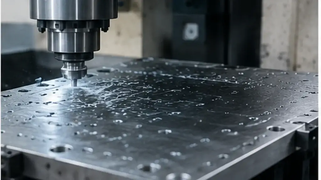
Flatness control starts before the final finishing pass.
Prepare suitable stock
The blank should allow sufficient machining allowance without requiring unnecessary material removal. Stock condition and thickness should match the plate geometry.
Establish the main reference face
The primary datum face should be created early enough to support subsequent operations, but final finishing may be delayed until the plate has undergone major material removal.
Use staged machining
A typical process may include:
- Initial face preparation
- Rough machining on the first side
- Rough machining on the opposite side
- Stress stabilization or controlled rest period where appropriate
- Semi-finishing
- Final datum and face finishing
- Precision hole and interface machining
- Free-state verification
This sequence can be adjusted according to geometry and material.
Balance material removal
Where the design permits, remove material from opposing sides in stages rather than completing one side before beginning the other.
Balanced removal cannot guarantee zero movement, but it helps reduce sudden stress redistribution.
Use distributed or low-distortion workholding
Vacuum fixtures, distributed supports or carefully controlled clamps may be used for wide plates.
The workholding method must prevent vibration without forcing the plate into an artificial shape.
Verify after release
A plate that is flat on the machine is not necessarily flat in its free state. Critical plates should be checked after unclamping and thermal stabilization.
When the plate will operate permanently bolted to a rigid machine frame, the drawing may also need an installed-condition requirement.
Flatness, Parallelism and Coplanarity
These requirements are related but not interchangeable.
Flatness
Flatness controls the shape of one surface. It does not require a datum.
A surface can satisfy flatness while not being parallel to the opposite mounting face.
Parallelism
Parallelism controls the orientation of one surface relative to a datum.
A fixture plate may require the upper equipment interface to remain parallel to the primary mounting surface.
Coplanarity
Coplanarity describes several separate surfaces that must function at a common height or plane.
Examples include:
- Three wafer support pads
- Multiple mounting bosses
- Sensor seats
- Vacuum support lands
Each pad may be individually flat but still sit at a different height from the others.
Thickness
Thickness controls the distance between opposite surfaces. It does not automatically guarantee that either surface is flat or that the two surfaces are parallel.
The drawing should specify the requirement that matches the functional risk instead of using flatness as a substitute for every relationship.
Hole Position and Datum Control
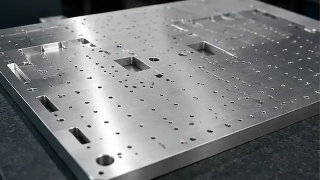
Hole systems on a semiconductor fixture plate often include locating, fastening, fluid and sensor functions.
Dowel holes
Dowel holes usually establish repeatable location. They may require control of:
- Diameter
- Fit
- True position
- Perpendicularity
- Relationship to datum surfaces
- Finished condition after treatment
A hole can pass a diameter gauge while still being too far from its theoretical location.
Clearance holes
Clearance holes allow fasteners to pass through. Their position requirements may be less restrictive unless they also control module alignment.
Applying dowel-hole tolerances to every clearance hole adds unnecessary machining and inspection.
Threaded holes
Threaded mounting holes require:
- Thread size
- Pitch
- Class
- Usable depth
- Position
- Treatment condition
When anodizing enters the threads, the final fit may change. Masking or post-treatment thread control should be defined where required.
Vacuum and process ports
These features may need size, location, sealing and cleanliness control. Burrs or chips inside intersecting passages can affect function even when the coordinate dimensions are correct.
Preserve one datum reference frame
Where possible, precision hole patterns and critical faces should be machined from a controlled datum strategy.
Repeatedly transferring datums between setups increases the risk of accumulated error. Five-axis or multi-face machining may reduce repositioning for some geometries, but the total method should be selected based on the relationship between features.
Surface Treatment Options
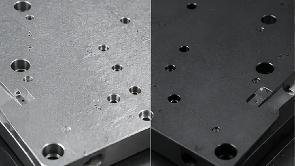
The correct surface treatment depends on wear, corrosion, electrical and cleanliness requirements.
As-machined
As-machined surfaces avoid coating buildup and may be appropriate for protected internal plates. Tool marks, corrosion behavior and cleaning requirements still need to be considered.
Type II anodizing
Type II anodizing is commonly used for corrosion protection and color. It may suit equipment covers, brackets and selected fixture plates.
The underlying machining finish remains visible, so anodizing should not be expected to hide chatter or deep tool marks.
Type III hard anodizing
Hard anodizing provides greater wear resistance and a thicker oxide layer. It may be used on contact, sliding or frequently handled surfaces.
Its dimensional effect is more significant than a thin decorative treatment and should be included in the tolerance plan.
Chemical conversion coating
Chemical conversion coating can provide corrosion protection while producing less dimensional buildup than anodizing. It may also be considered where electrical conductivity or grounding is important.
The exact treatment should follow the equipment and customer specification.
Electroless nickel plating
Electroless nickel may provide corrosion resistance, hardness and more uniform coverage on complex surfaces.
Plating thickness can change holes, pads and sealing features. The substrate preparation and final surface condition should be defined.
Selective masking or post-machining
Critical areas that may require masking include:
- Dowel holes
- Precision bores
- Grounding points
- Electrical contact areas
- Support pads
- Sealing lands
- Threaded holes
Another option is to finish selected features after surface treatment. This adds another operation but can establish the final fit directly in the treated condition.
How Surface Treatment Changes Final Geometry?
Surface finishing is part of the dimensional process, not a separate cosmetic step.
Treatment can affect:
- Hole diameter
- Shaft or boss size
- Thread fit
- Pad height
- Surface roughness
- Electrical contact
- Vacuum sealing
- Flatness
- Coplanarity
Anodizing converts part of the aluminum surface into oxide and also grows outward. The actual dimensional change depends on alloy, pretreatment, coating type and process conditions.
Precision features should therefore be identified as:
- Controlled before treatment
- Controlled after treatment
- Masked
- Re-machined after treatment
A pre-treatment dimension report does not prove that the finished component still meets the final drawing.
Inspection After Machining and Finishing
A useful inspection plan separates dimensional size from geometric relationships.
| Feature | Verification focus |
| Main surface | Flatness in the specified support condition |
| Opposite surface | Parallelism and thickness |
| Support pads | Coplanarity |
| Dowel holes | Diameter and true position |
| Hole patterns | Position relative to datums |
| Threads | Functional thread fit and usable depth |
| Vacuum grooves | Width, depth, burrs and sealing surface condition |
| Surface treatment | Thickness, coverage, masking and appearance |
| Final plate | Post-treatment geometry and cleanliness |
Define the measurement condition
The inspection requirement should state:
- Free state or restrained state
- Support-point arrangement
- Measurement temperature
- Before or after treatment
- Datum alignment
- Measurement grid or point distribution
- Reporting format
A large surface measured at only a few points may not adequately represent its shape.
Use the appropriate measurement method
CMM can be valuable for:
- Datum alignment
- Hole-axis position
- Parallelism
- Coplanar pads
- Complex profiles
Surface plates, indicators, height instruments, optical systems and functional gauges may also be appropriate depending on the feature.
The inspection method should follow the required uncertainty and feature access rather than rely on one instrument for every characteristic.
Cleaning, Packaging and Handling
Machining accuracy can be lost after final inspection if the plate is poorly cleaned or packaged.
The manufacturing plan should address:
- Chips in blind holes or vacuum channels
- Burrs around grooves and ports
- Oil or residue on contact surfaces
- Separation between treated surfaces
- Protection of precision pads and holes
- Support of large thin plates during shipment
- Part number and revision identification
- Clean packaging requirements specified by the customer
Large plates should not be tightly strapped or supported at unsuitable points in a way that introduces permanent deformation.
Packaging requirements should be defined in the RFQ when surface condition or cleanliness is critical.
Three Semiconductor Fixture Plate Examples
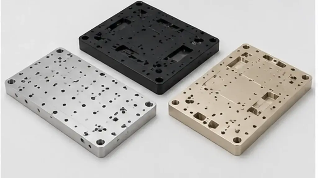
Wafer Handling Fixture
A wafer fixture may contain several raised support pads and robot pickup references.
The key requirements may include:
- Pad coplanarity
- Overall support-face flatness
- Pickup-feature location
- Low-burr edges
- Hard-anodized wear surfaces
- Masked contact pads
- Post-treatment inspection
The support geometry should be inspected in the same functional datum system used by the handling equipment.
Equipment Alignment Plate
An alignment plate may connect a motion stage to the machine frame.
Its critical features may include:
- Primary mounting face
- Parallel upper interface
- Dowel-hole pattern
- Threaded fastening holes
- Sensor mounting locations
The locating holes should be machined and inspected relative to the primary datums rather than treated as independent coordinate dimensions.
Vacuum Process Plate
A vacuum plate may include grooves, ports, sealing lands and precision mounting holes.
Manufacturing control should address:
- Surface flatness
- Groove width and depth
- Sealing-land roughness
- Intersecting passages
- Burr and chip removal
- Surface-treatment compatibility
- Protective packaging
A dimensional inspection alone may not detect contamination or a burr that prevents reliable vacuum sealing.
Information Required for an Accurate Quote
For an accurate semiconductor CNC machining quotation, provide:
- STEP or STP model
- 2D engineering drawing
- Part number and revision
- Material grade and temper
- Finished plate dimensions
- Primary datums
- CTQ features
- Flatness and parallelism requirements
- Free-state or installed inspection condition
- Dowel-hole fits and position tolerances
- Surface roughness
- Surface-treatment type and thickness
- Masking requirements
- Pre-treatment and post-treatment dimensions
- Inspection-report scope
- Cleaning and packaging requirements
- Prototype and production quantities
The quotation should identify any assumptions concerning support condition, masking, coating buildup and final inspection.
How SinoRise Supports Semiconductor Fixture Plate Machining?
SinoRise reviews fixture plates as complete manufacturing systems rather than isolated dimensions. The engineering plan can connect material selection, datum control, staged machining, precision holes, surface finishing and post-treatment inspection.
SinoRise operates more than 40 precision machining machines and uses inspection equipment including 2.5D measuring systems, digital height gauges and CMM equipment. Its ISO 9001 quality system supports projects in semiconductor equipment, medical equipment, UAVs, robotics, optical instruments and automotive or motorcycle components.
For critical plates, the drawing review should confirm the final inspection state, surface-treatment compensation and required reporting before production begins.
Frequently Asked Questions
What material is best for a semiconductor fixture plate?
The choice depends on stability, strength, thread loading, anodizing, thermal behavior and final use. 6061-T651 and cast tooling plate are common options to evaluate.
Is cast tooling plate always better than 6061?
No. Cast tooling plate may offer better dimensional stability for extensive face machining, while 6061 may provide better structural strength, thread performance and anodizing characteristics.
Why does an aluminum plate warp after milling?
Residual stress, asymmetric material removal, clamping force, machining heat and thin geometry can cause movement after the plate is released.
Should flatness be measured free or clamped?
The drawing should specify the relevant condition. Free-state flatness may matter for independent fixtures, while installed performance may also matter for permanently bolted plates.
What is the difference between flatness and parallelism?
Flatness controls one surface by itself. Parallelism controls one surface relative to a datum.
How is hole position inspected?
Critical hole position is commonly evaluated relative to the specified datum reference frame using CMM, optical measurement or a functional gauge.
Does anodizing affect plate flatness?
It can contribute to final dimensional changes, especially on large or thin plates. Critical flatness should be verified after the specified surface treatment.
Does anodizing make precision holes smaller?
Coating buildup can reduce an internal hole’s effective diameter. The amount depends on the anodizing process and should be addressed through compensation, masking or post-treatment machining.
Should dowel holes be masked?
Masking may be appropriate when the final fit cannot tolerate coating buildup. The drawing should specify the required finished condition.
Should fixture plates be inspected after surface treatment?
Critical finished dimensions, hole fits, flatness, coplanarity and threads should generally be verified in the condition required for final assembly.
Request a Semiconductor Fixture Plate Review
Send SinoRise your model, drawing, material, datum structure, flatness requirements, hole tolerances, surface treatment and inspection scope.
The engineering team will review material stability, machining sequence, treatment compensation and post-finish verification before quotation.