
Complex automotive engine brackets are CNC machined by converting an engineering drawing into a carefully planned sequence of milling, drilling, finishing, and inspection operations. Because these brackets often have mounting faces at different angles, reinforced pockets, and precisely located holes, the machining process must preserve the relationship between these features as material is removed.
The work usually begins with reviewing the part geometry and tolerances, followed by material preparation, datum selection, fixture design, rough milling, and finishing of the mounting features. The finished bracket is then inspected against its drawing requirements. Throughout this process, the main concern is not simply producing the correct shape, but ensuring that the part fits its intended assembly.
What Makes Automotive Engine Brackets Difficult to CNC Machine?
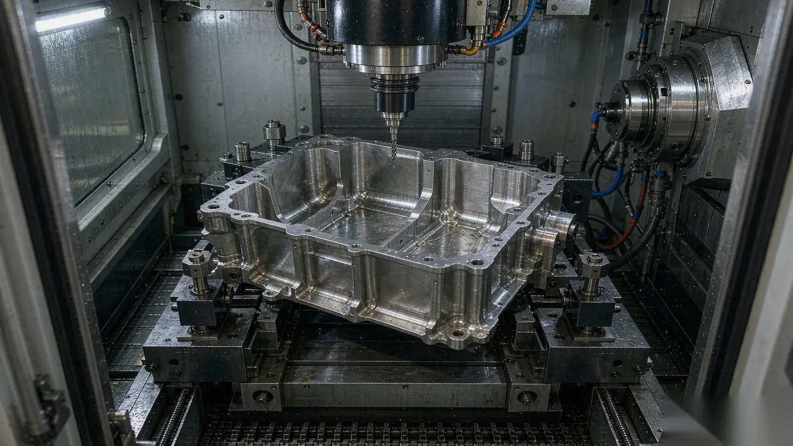
An engine mounting bracket must accommodate the available installation space while providing suitable connections between the engine and its supporting structure. Its geometry may include mounting faces at different heights or angles, reinforcing ribs, recessed areas, and holes positioned along several directions. Each feature serves a purpose, but their combination can make the component difficult to machine.
One common difficulty is tool access. A milling cutter may reach an exposed mounting surface easily, yet struggle to enter a narrow pocket beside a reinforcing rib. Deep recesses can require longer tools, increasing the risk of deflection or vibration. Angled surfaces and side-facing holes may also be inaccessible without rotating or repositioning the workpiece.
The bracket's mounting geometry presents a different problem. A component can have acceptable external dimensions but still fail to fit if its mounting holes are not positioned correctly relative to the contact surfaces. For this reason, critical holes and mating faces must be considered together rather than machined as unrelated features.
Weight-reducing pockets add another concern. As material is removed from a solid blank, the remaining walls and ribs become less rigid. Cutting forces and clamping pressure that were acceptable during roughing may affect the part differently during finishing. A successful machining plan must therefore account for how the workpiece changes throughout production, especially where thin sections support critical mounting features.
How Do Materials and Drawing Requirements Affect Engine Bracket Machining?
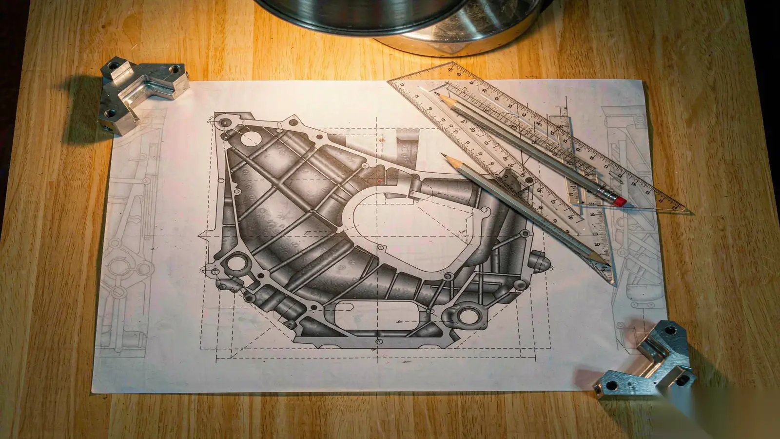
Before selecting tools or preparing a CNC program, engineers need to understand the specified material and the dimensions that determine the bracket's function. These two factors influence both the machining method and the way the finished component will be evaluated.
Aluminum alloys are common candidates for lightweight machined brackets. Aluminum 6061-T6 offers good machinability and corrosion resistance, while 7075-T6 provides higher strength where its properties are appropriate for the design. Carbon and alloy steels may be selected when their mechanical characteristics better suit the loading and installation conditions.
| Material | Main Characteristics | Machining Considerations |
| Aluminum 6061-T6 | Good machinability, moderate strength, corrosion resistance | Suitable for many lightweight machined components |
| Aluminum 7075-T6 | Higher strength than 6061-T6 | Material cost, corrosion protection, and service conditions |
| Carbon or Alloy Steel | Wide range of strength and stiffness properties | Higher cutting forces, tool wear, and possible heat-treatment requirements |
Material selection cannot be based on machining convenience alone. The design must also account for expected loads, fatigue behavior, operating temperature, environmental exposure, and any applicable engineering requirements.
The next step is to review the 3D model alongside the 2D drawing. The model helps identify machining directions and areas with restricted tool access, while the drawing establishes material requirements, tolerances, datum references, and the features that matter most during assembly.
This distinction is especially important for mounting holes. Two holes can have the correct diameter and spacing but still be incorrectly positioned relative to the bracket's installation face. A conventional dimension check may not reveal that error if the drawing specifies a geometric position tolerance.
The ASME Y14.5 standard describes the purpose of geometric dimensioning and tolerancing in terms of “form, fit, function and interchangeability.” For an engine bracket, these principles connect directly to the mounting surfaces and locating holes: the individual features must meet their specifications while maintaining the relationships needed for assembly.
By identifying these requirements before machining, engineers can decide which surfaces should serve as references, which features need finishing allowances, and where more detailed dimensional inspection will be necessary.
How Are Machining Datums and Fixtures Established for Complex Engine Brackets?
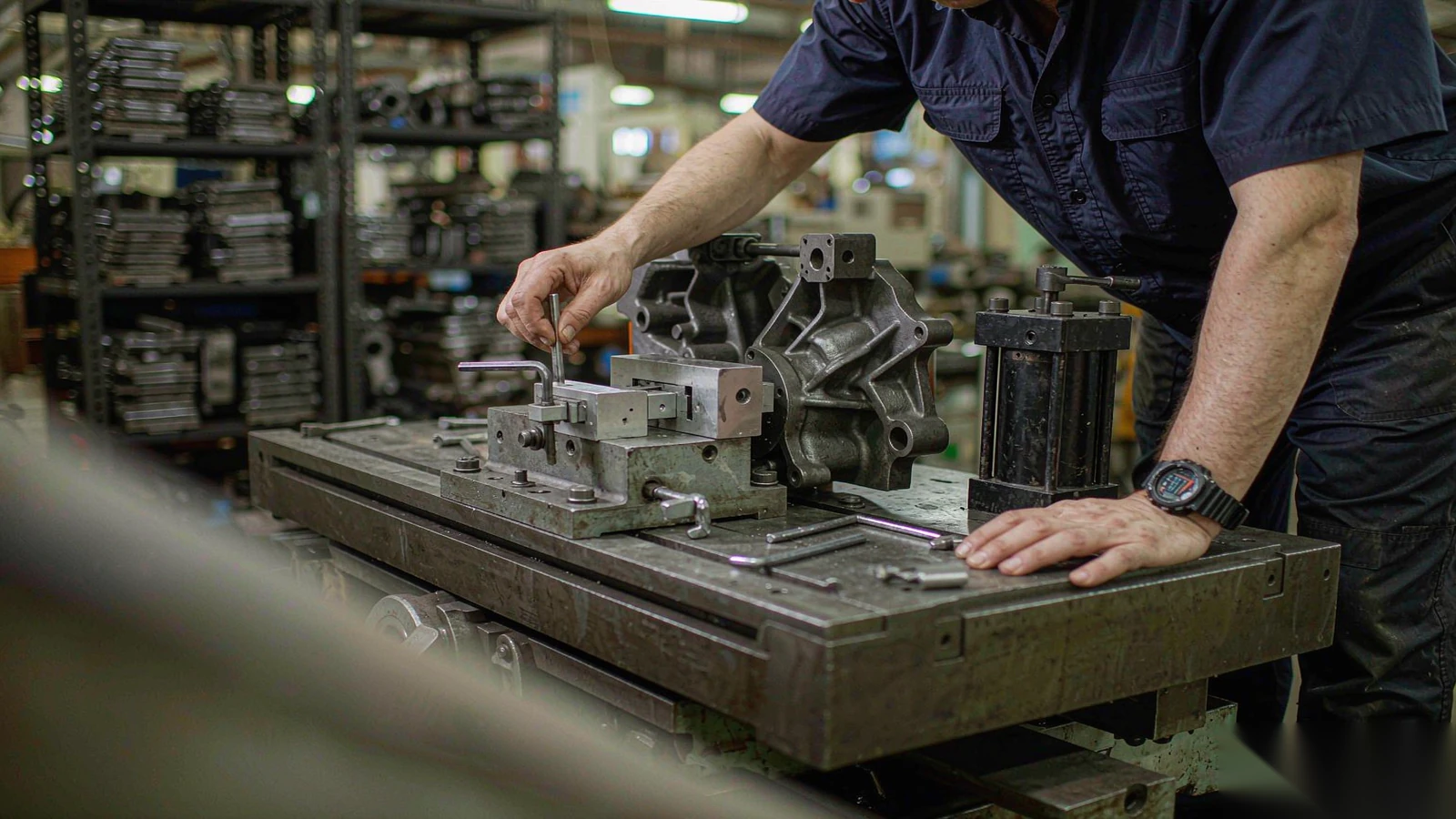
The machining strategy becomes more challenging when critical features cannot be produced from a single direction. In these cases, maintaining a reliable reference between setups is essential, particularly when a hole pattern on one face must align with a mounting surface on another.
3.1 Selecting Functional Datums and Locating Surfaces
Datum planning starts with the engineering drawing. A broad installation face may provide a suitable primary reference, while designated locating holes or other features can help establish the remaining position and orientation of the bracket.
However, the initial workpiece may not offer a sufficiently accurate locating surface. When machining from a billet or an irregular casting, the first operation may be used to prepare a stable reference face. This allows subsequent features to be machined from a more consistent setup.
Machining references do not always have to be identical to the design datums, but their relationship must remain controlled. If the bracket is repositioned for a side-facing hole, for example, the new setup needs to preserve the relevant geometry established during earlier operations. Otherwise, the error introduced during relocation may affect the final hole position.
3.2 Planning Fixtures and Multiple Setups
A fixture must hold the bracket securely without blocking the areas that need machining. It also needs to support the workpiece where cutting forces might cause movement or deflection.
The 3-2-1 locating principle is a useful starting point for understanding how workpiece movement can be constrained. Actual fixture designs, however, depend on the bracket's geometry. An irregular component may require shaped locating elements or additional support near a thin wall, while a more conventional bracket may be held using simpler fixtures.
Clamping pressure deserves particular attention. Applying force to an unsupported section can temporarily distort the workpiece, and the resulting dimensional error may only become apparent after the clamps are released. Supporting more rigid regions and keeping clamps clear of toolpaths can reduce this risk.
When a second setup is needed, repeatable locating features are generally more useful than relying on the external contour alone. The fixture arrangement should allow the machinist to reposition the bracket consistently while keeping the important mounting features accessible.
What Are the Main CNC Milling Steps for an Automotive Engine Bracket?
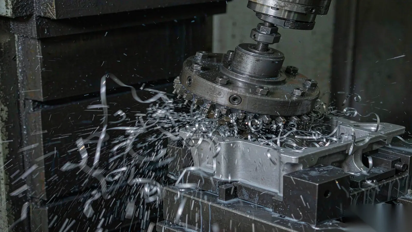
Once the machining references and workholding arrangement have been established, the bracket can move into production. Although the exact sequence depends on whether the starting material is a billet, forging, or casting, most complex machined brackets follow a progression from rough material removal to finishing the functional surfaces and holes.
4.1 Rough Milling and Establishing Reference Surfaces
Rough milling removes excess stock and creates the basic shape of the component. For a bracket machined from a billet, this may involve facing the material, opening larger pockets, and cutting around the main outer profile.
Rather than finishing each area immediately, machinists typically leave appropriate allowances on critical features. This creates an opportunity to address dimensional changes that occur as material is removed, especially when the bracket contains large pockets or relatively thin sections.
The roughing sequence should also account for the distribution of material. Removing a substantial amount from one side of a workpiece may release residual stresses and change its shape. When such movement is a concern, roughing can be separated from final finishing, with the workpiece checked or allowed to stabilize as required by the process.
4.2 Machining Mounting Faces, Pockets, and Complex Profiles
After roughing, the milling operations focus on producing the bracket's mounting faces, recessed features, and final contours. Flat surfaces may be accessible through conventional face milling or end milling, while angled faces and pockets near reinforcing ribs require closer attention to tool direction and clearance.
For a bracket with accessible geometry, a 3-axis machining center may be entirely suitable. Additional setups can expose features on other sides, provided that the locating arrangement maintains the required accuracy.
More complicated geometries may benefit from 5 axis CNC machining. As Autodesk explains, multi-axis machining “reduces the number of setups required.” This advantage is relevant to engine brackets with mounting features oriented in different directions: fewer transfers can reduce the number of times the workpiece must be relocated, although the fixture and machine still need to maintain suitable accuracy.
Indexed 3+2 machining may be sufficient for brackets with several angled but otherwise conventional surfaces. Simultaneous five-axis movement is more appropriate where the geometry requires continuous changes in tool orientation. Neither method is automatically necessary for every complex-looking bracket; machine selection should follow the actual features and tolerance requirements.
CAM programming must also consider the space around ribs, pocket walls, and clamping elements. Appropriate tool lengths, collision checks, and cutting conditions help ensure that the selected approach is practical before machining begins.
4.3 Finishing Critical Holes and Threaded Features
The mounting and locating holes are usually finished with particular attention to their size and position. Bolt-clearance holes may be drilled if the required tolerance permits, while locating holes with tighter size or geometric requirements may need reaming or boring.
Threaded holes introduce separate considerations. Depending on the material, thread dimensions, and available clearance, they may be produced using tapping or thread milling. The chosen method must provide the required thread quality without damaging surrounding features.
For brackets with holes on different faces, the finishing sequence should follow the datum strategy established earlier. The objective is to produce the holes in the correct relationship to the relevant mounting surfaces, not merely to achieve their individual diameters.
After these operations, the bracket is deburred and cleaned. Particular care is needed around contact faces, hole openings, and threads, where remaining burrs could interfere with assembly or measurement.
How Are Hole Position and Tolerances Controlled in CNC Machined Engine Brackets?

Hole position is often more difficult to control than hole diameter, especially when the related features are machined in different setups.
Consider a bracket with a flat engine-side mounting face and a second attachment face at an angle. The first face may be machined accurately, but a small locating error during the next setup could shift the second hole pattern relative to the specified datums. Even if every hole meets its diameter tolerance, the finished bracket may not satisfy its positional requirements.
The machining process must therefore account for errors introduced by workpiece relocation, tool deflection, cutting forces, and material movement. The influence of each factor depends on the bracket's geometry and the tolerances assigned to its features.
For example, a thin wall may deflect slightly under cutting pressure, while a deep pocket may require a longer tool that is less rigid. Adjusting tool selection, cutting conditions, and workholding support can help control these effects. Where large amounts of material have been removed, an intermediate dimensional check may also be useful before the final machining pass.
Not every feature requires the same level of accuracy. A general external profile may have a relatively broad tolerance, while a locating hole or mating face may require much closer control. The engineering drawing should make these differences clear so that machining effort is concentrated on the features that affect the bracket's function.
Rather than applying an arbitrary precision value across the entire part, manufacturers should evaluate each critical requirement using the appropriate datum reference frame and geometric tolerance.
How Are CNC Machined Engine Brackets Inspected Before Delivery?
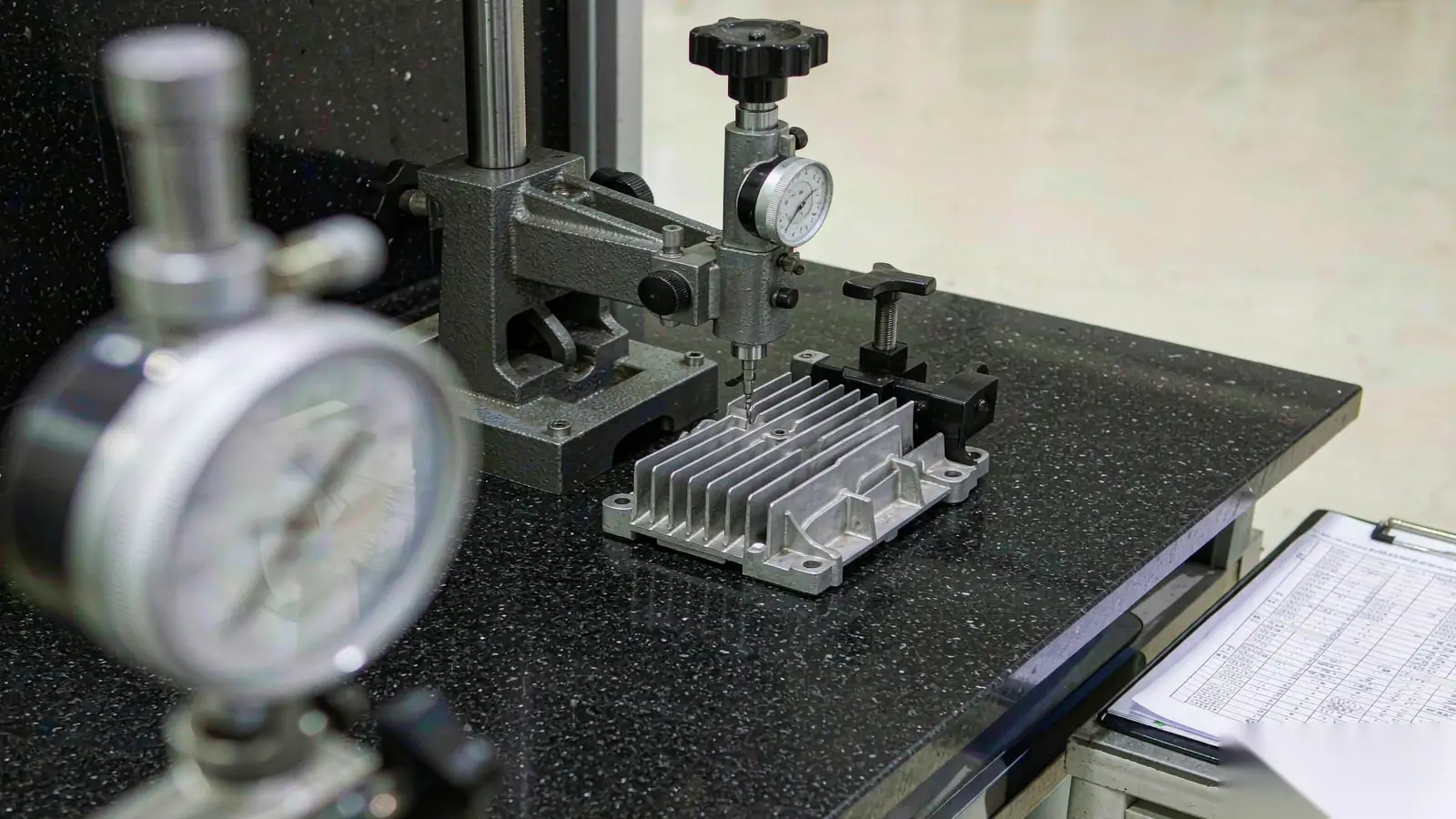
The purpose of final inspection is to confirm that the finished bracket satisfies the drawing requirements, particularly those associated with mounting and alignment. Checking overall length and width alone is insufficient when the component contains multiple installation surfaces and precisely located holes.
A coordinate measuring machine (CMM) is useful for inspecting complex brackets because it can evaluate features relative to a defined datum reference frame. For example, the inspector can establish the specified references and then determine whether the mounting hole pattern satisfies its positional tolerance. This provides more meaningful information than measuring hole spacing independently when the drawing requires a datum-based evaluation.
Other measuring instruments remain suitable for features that can be checked directly.
| Inspection Feature | Typical Method | Inspection Purpose |
| Mounting hole position | CMM | Evaluate hole locations relative to specified datums |
| Mounting surface flatness | CMM or suitable surface measurement method | Check the form of installation faces |
| Precision hole diameter | Bore gauge, plug gauge, or CMM | Verify required hole sizes |
| External dimensions | Height gauge, calipers, or CMM | Check specified overall dimensions |
| Threaded holes | Thread gauges | Verify applicable thread requirements |
For a newly developed bracket, first-article inspection can help establish whether the planned machining process produces acceptable dimensions. During production, additional checks may be needed where tool wear or repeated setups could affect critical features.
Surface finishing must also be considered before parts are accepted. Anodizing or plating can affect certain dimensions, particularly those involving close fits or threads. Depending on the drawing, these features may require protection during finishing or verification afterward.
Inspection documentation should reflect the intended application and customer requirements. Prototype components may require detailed dimensional reports, while repeated orders may follow an agreed inspection and sampling plan.
What Should Engineers Check Before Ordering Custom CNC Engine Brackets?
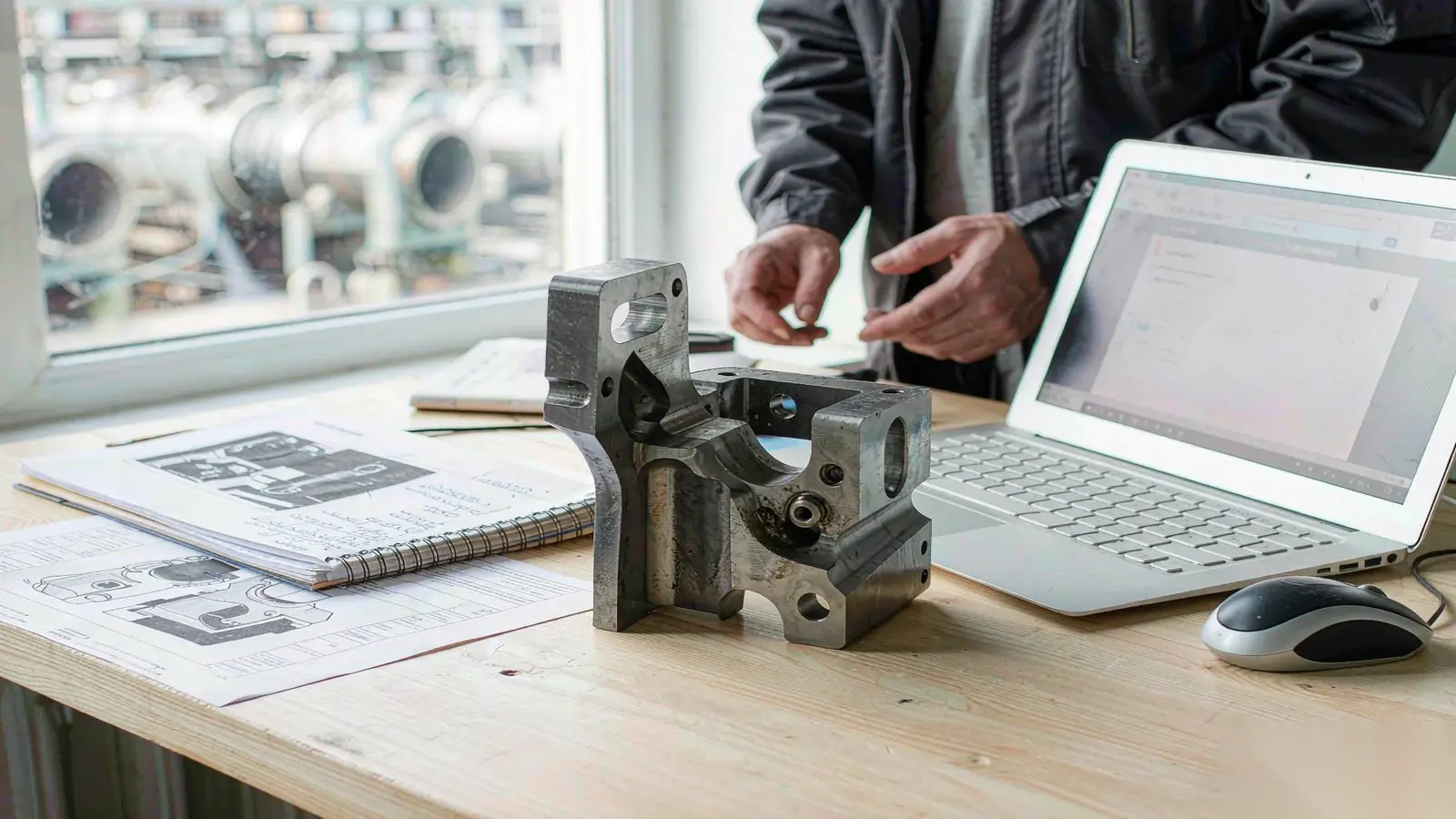
A complete drawing package helps identify machining difficulties before the bracket reaches production. In addition to a 3D CAD model, engineers should provide a 2D drawing showing the specified material, datum references, geometric tolerances, surface treatment, and critical assembly features.
The expected order quantity also matters. A fixture that is practical for a short prototype run may not be the most efficient choice for repeated small-batch production. Similarly, demanding positional tolerances may influence how the bracket is held, machined, and inspected.
For a bracket with angled mounting surfaces or multiple locating holes, reviewing these requirements before quotation can reveal whether conventional milling with several setups is sufficient or whether a multi-axis approach would be more appropriate.
At SinoRise, a custom engine bracket inquiry can begin with this type of drawing review. Identifying the critical mounting features and the required inspection criteria early helps determine a machining approach suited to the part, rather than selecting equipment based on its external complexity alone.
Frequently Asked Questions
Can a complex engine bracket be machined on a 3-axis CNC machine?
Yes. Many engine brackets can be machined using 3-axis equipment, provided the required surfaces are accessible through suitable setups. Angled faces and side-facing holes may require repositioning, so the fixture and datum strategy must maintain the required relationships between features. Five-axis machining becomes an option when additional tool orientations offer a practical benefit.
When is 5-axis CNC machining necessary for engine brackets?
Five-axis machining is useful when mounting faces or recessed features are difficult to reach using conventional tool directions. Indexed 3+2 operations can often machine features from several angles without continuous simultaneous movement. The decision should consider tool access, positional accuracy, setup time, and production quantity rather than part shape alone.
How can thin-wall deformation be reduced during CNC milling?
Thin sections should be supported appropriately and machined with cutting conditions that limit unnecessary forces. A roughing strategy that leaves material for finishing may help account for distortion caused by stock removal. Where deformation is a significant concern, intermediate measurement can be used to assess the workpiece before its critical features are finished.
What information is required to quote a custom engine bracket?
A quotation generally requires 2D engineering drawings, 3D CAD files, material specifications, tolerances, surface treatment requirements, and order quantity. Critical mounting features and inspection requirements should also be identified, especially when the bracket must fit precisely within an existing assembly.
Conclusion
Machining a complex automotive engine bracket involves more than producing its external geometry. The choice of material, the way the workpiece is located, the order of milling operations, and the inspection of critical features all influence whether the finished component meets its assembly requirements.
For custom engine brackets, reviewing the drawing with these manufacturing considerations in mind can help identify suitable machining methods and avoid unnecessary difficulties during production.
References
ASME Y14.5 – Dimensioning and Tolerancing — Referenced in the drawing requirements section for the functional purpose of GD&T.
Autodesk – 5-Axis Machining — Referenced in the milling section for the benefits of reducing machining setups.
MIT OpenCourseWare – Design and Manufacturing II — Additional technical reading on workholding and fixture principles.