
Automotive brackets often combine several demanding features in a compact metal component: accurately positioned mounting holes, recessed pockets, reinforcing ribs, and surfaces facing different directions. Although these features may be necessary for strength, weight reduction, or assembly, their arrangement has a direct effect on CNC milling.
A bracket with accessible pockets and conventional mounting holes may be relatively straightforward to manufacture. Another bracket of similar size could require longer cutting tools, multiple setups, or additional finishing operations because of narrow cavities and restricted tool access.
Design for manufacturability (DFM) helps engineers identify these differences before the drawings are released. This guide covers the fundamentals of CNC milling automotive brackets, from material and machining method selection to hole design, pocket geometry, wall thickness, finishing requirements, and cost considerations.
What Is CNC Milling Design for Automotive Brackets?
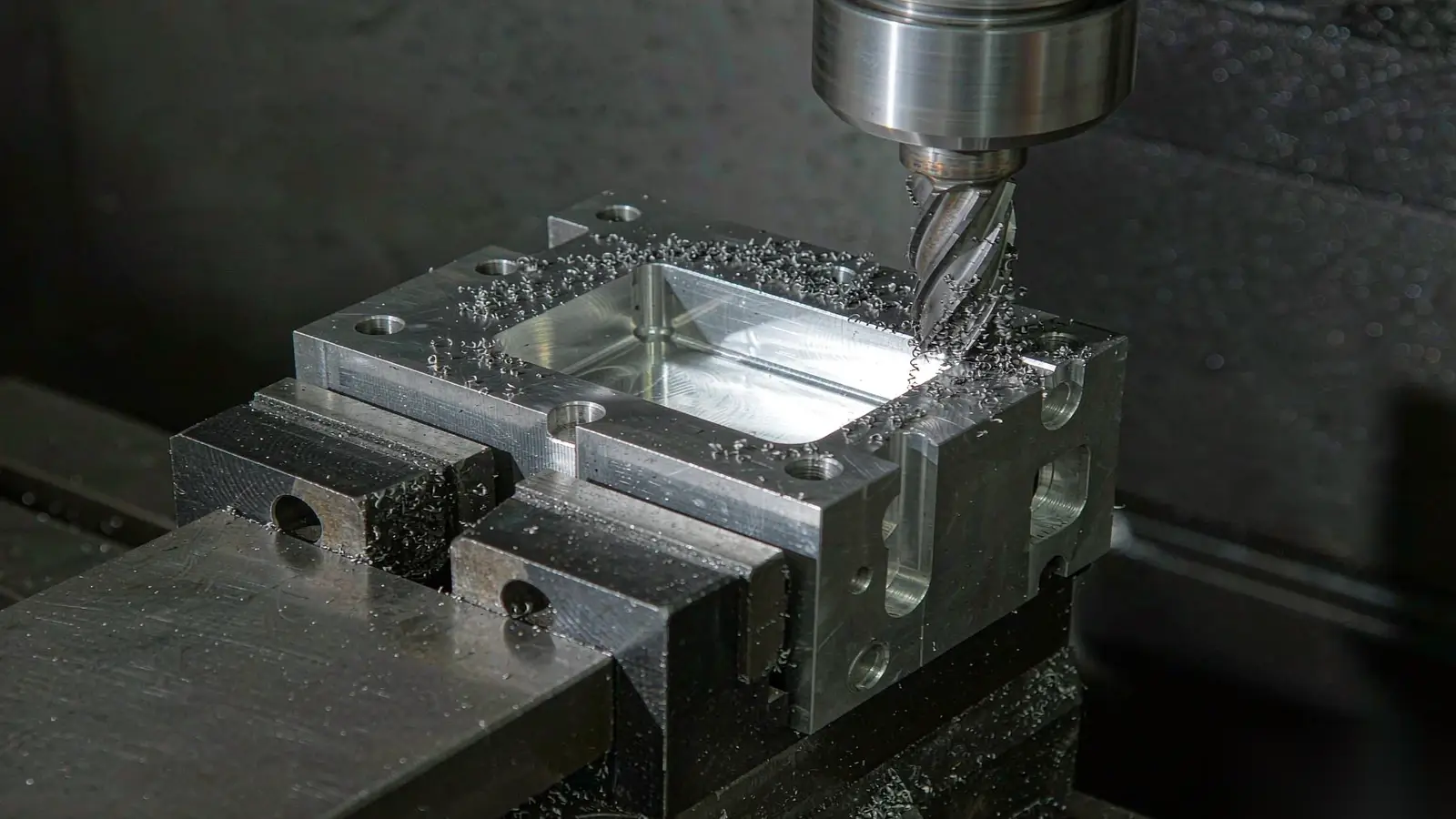
CNC milling is a subtractive manufacturing process that uses rotating cutting tools to shape metal workpieces. It can produce flat mounting faces, drilled holes, recessed pockets, and complex external profiles, making it useful for automotive brackets requiring accurate interfaces or custom geometries.
Engine brackets, transmission supports, brake system brackets, and sensor mounts are examples of components that may be manufactured using CNC milling. Their dimensions and performance requirements differ, but many share similar geometric features, including bolt patterns, supporting ribs, and precisely defined contact surfaces.
1.1 How CNC Milling Requirements Influence Bracket Geometry
Every milled feature must be accessible to a suitable cutting tool. The tool's diameter affects the smallest internal corners it can produce, while its length determines how deeply it can reach into a cavity. Surrounding ribs and walls can further restrict the available approach directions.
Workholding adds another consideration. The bracket needs stable locating and supporting areas so it can resist cutting forces without excessive movement. An irregular design with limited supporting surfaces may require more elaborate fixtures than a part with accessible reference faces.
These constraints are best considered during CAD development. A feature that appears simple in a model can become difficult to manufacture when the required cutting tool or fixture cannot reach it.
1.2 Benefits and Limitations of CNC Milled Automotive Brackets
CNC milling is particularly useful for prototypes, custom components, and low-volume production. Engineers can revise designs without investing in new casting or stamping dies, and parts can be produced directly from suitable engineering materials.
The process also allows mounting interfaces to be machined to their specified dimensional requirements. However, material removal can become time-consuming when a bracket contains extensive pockets, while restricted access or demanding surface geometry may require more complex machining arrangements.
For higher production quantities, casting, forging, or stamping may become economical alternatives, sometimes combined with CNC finishing of critical mounting features. The appropriate process depends on the design, material, volume, and expected product lifecycle.
Which Materials and CNC Milling Methods Suit Automotive Brackets?
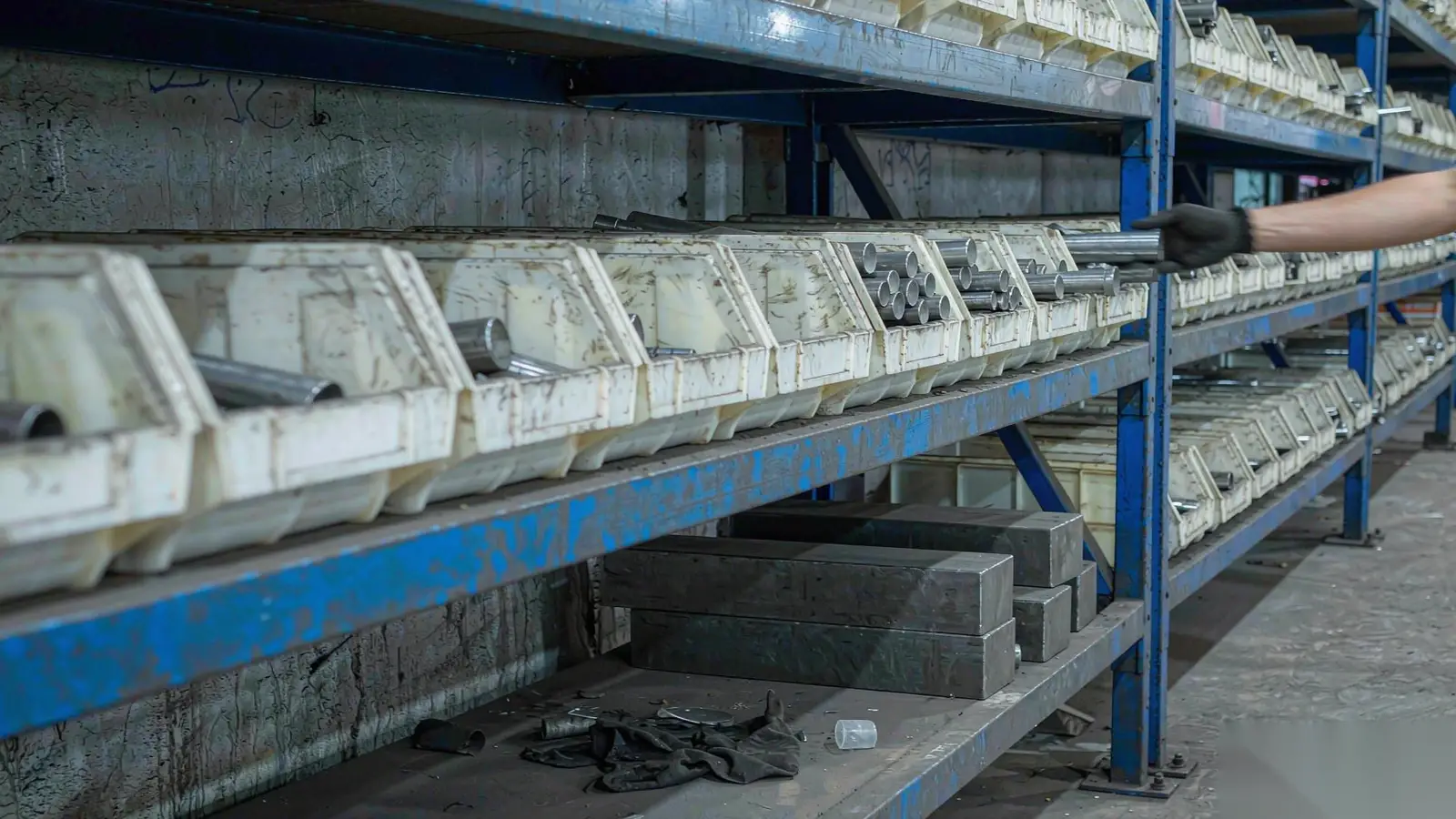
Material selection starts with the bracket's operating conditions. Mechanical loads, stiffness, weight targets, fatigue requirements, temperature, and corrosion exposure all influence which metal is suitable. Machinability matters, but it should not override the component's functional requirements.
2.1 Common Materials for Automotive Bracket CNC Milling
Aluminum alloys are often considered when weight reduction is important. Aluminum 6061-T6 combines good machinability with useful mechanical properties and corrosion resistance, while 7075-T6 offers higher strength for applications where its characteristics are appropriate.
Steel remains relevant when its strength, stiffness, durability, or connection requirements better suit the design.
| Material | Typical Characteristics | Design Considerations |
| Aluminum 6061-T6 | Good machinability, moderate strength, corrosion resistance | Suitable when its strength and stiffness meet the application |
| Aluminum 7075-T6 | High strength relative to weight | Cost, corrosion behavior, fatigue and environmental conditions |
| Carbon Steel | Broad range of available mechanical properties | Weight, corrosion protection, joint design |
| Alloy Steel | Properties can be adjusted through grade selection and heat treatment | Material condition, strength requirements, machining behavior |
A higher-strength material does not necessarily eliminate the need for supporting ribs or adequate wall thickness. The bracket's geometry and load distribution must still be validated.
2.2 When to Consider 3-Axis or Multi-Axis Milling
Many brackets can be machined using 3-axis equipment, especially when their pockets and mounting features are accessible from conventional tool directions. Features on opposite sides or inclined faces may require additional setups.
Indexed 3+2 machining allows the tool to approach features from different fixed orientations, while simultaneous five-axis machining is suited to certain complex surfaces requiring continuous changes in tool direction.
The choice should be based on the geometry rather than the apparent complexity of the finished part. A bracket with several angled mounting faces may benefit from multi-axis access, whereas one with simple planar features may be produced economically using conventional milling and repeatable workholding.
How Should Mounting Holes, Threads, and Tolerances Be Designed?
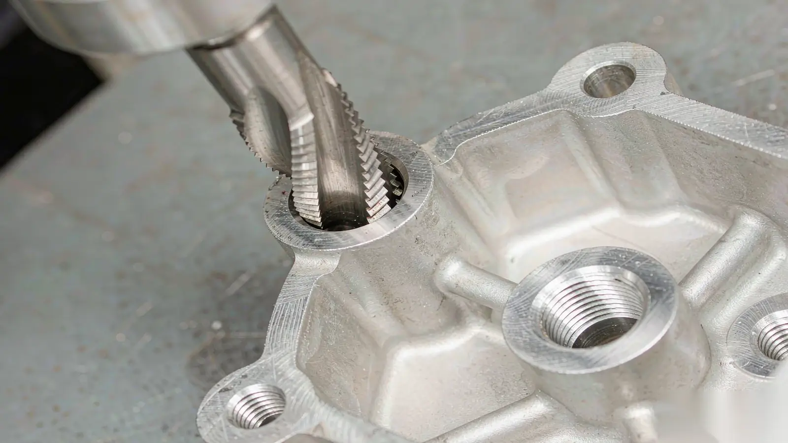
Hole design begins with the bracket's assembly requirements. Fastener positions and locating features must match their mating components, but engineers can still optimize hole depth, local clearance, and the way precision requirements are communicated.
3.1 Hole Depth, Thread Engagement, and Fastener Access
Deep blind holes can be more demanding than short holes because chips must be removed through a confined drilling path. The difficulty increases with depth relative to diameter, although the practical machining limit varies with tool type, material, coolant delivery, and equipment.
Threaded holes need sufficient effective engagement for the chosen fastener and joint loading. Adding thread depth without a mechanical reason can create extra manufacturing work, particularly in blind holes that also require clearance beyond the full thread.
The surrounding geometry should be checked at the same time. A mounting hole close to a reinforcing rib may provide enough space for drilling but restrict a counterbore tool or prevent a socket from reaching the fastener. Reviewing the entire fastener installation space can reveal these conflicts before machining.
3.2 Functional Tolerances and GD&T
Not every dimension on an automotive bracket needs the same level of precision. Mounting faces, locating holes, and interfaces controlling assembly alignment deserve particular attention, while nonfunctional pocket walls or exterior contours may allow broader limits.
ASME Y14.5 describes GD&T as a language for communicating design intent, including “form, fit, function and interchangeability.” For a bracket with multiple installation points, this means that the drawing should clearly define the relationships between the mounting faces and hole patterns through appropriate datum references.
For example, two holes can have acceptable individual diameters but still fail to meet their positional requirements relative to the mounting surface. A well-defined datum reference frame allows those relationships to be manufactured and inspected consistently.
Rather than assigning tight limits across the entire part, the designer should identify which deviations would affect assembly or performance and specify the corresponding geometric requirements.
How Do Pocket Depth, Corner Radii, and Tool Access Affect CNC Milling?
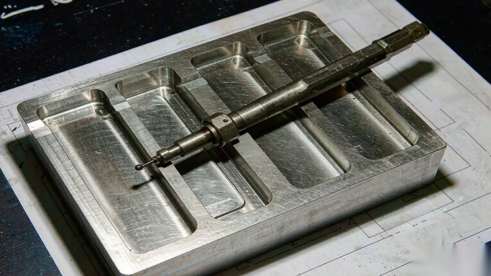
Pockets are frequently introduced to reduce weight or create clearance around neighboring components. Their shape influences both the remaining structure of the bracket and the tools needed to machine it.
4.1 Pocket Depth and Internal Corner Radii
A deep, narrow cavity may require a relatively small end mill with a long unsupported cutting length. This can increase the risk of tool deflection and vibration, particularly when finishing pocket walls.
Sandvik Coromant's milling application guidance identifies “Shortest possible tool length” among the main considerations for machining stability. For bracket designers, the practical implication is that pocket depth and opening width should be assessed together. A cavity that accommodates a shorter, more rigid tool may allow more efficient milling.
Internal corner radii affect cutter selection in a different way. Conventional cylindrical end mills leave a rounded internal corner, and specifying a smaller radius generally requires a smaller finishing tool. When a cavity serves only as a weight-reduction feature, very small corner radii may add unnecessary machining work.
Larger permissible radii or localized reliefs can sometimes improve manufacturability. These changes must still respect local stress distribution and the space needed by mating components.
4.2 Tool Accessibility Around Ribs and Angled Features
Tool access depends on the complete surrounding geometry, not just the dimensions of the feature being cut. A pocket may be wide enough for the cutter yet too restricted for its holder. Similarly, an inclined mounting surface can require another tool approach when neighboring ribs prevent access from the initial direction.
During design review, engineers can examine whether noncritical walls, ribs, or clearance areas can be repositioned without changing the bracket's function. In some cases, a small geometric revision creates enough space for conventional milling; in others, a different machining orientation remains necessary.
Keeping these access requirements visible during CAD development provides more flexibility in selecting a suitable manufacturing method.
How Should Wall Thickness and Ribs Be Designed for CNC Milled Brackets?

Wall thickness should be established from the bracket's mechanical requirements and then checked for manufacturing stability. There is no universal minimum thickness that applies to every aluminum or steel automotive bracket.
5.1 Thin Walls and Machining Stability
The behavior of a thin wall depends on more than its thickness. A short wall supported along its base can be comparatively stable, while a tall rib of identical thickness may deflect under lateral cutting forces.
The surrounding material also influences stability. As material is removed from a weight-reduction pocket, neighboring sections lose some of their original support. This can make slender walls more sensitive to clamping forces, vibration, and the final cutting passes.
Sandvik Coromant's milling guidance advises supporting the workpiece against cutting forces and selecting a machining strategy that promotes stability. For bracket design, this reinforces the importance of evaluating unsupported wall height and local support, rather than treating nominal thickness as the only relevant dimension.
5.2 Rib Geometry and Material Distribution
Reinforcing ribs can provide stiffness without making an entire bracket solid. Their placement should reflect the expected load paths, particularly around mounting points and transitions between structural sections.
Where the design allows, material may be retained near the base of a slender rib or distributed through smoother transitions between thick and thin sections. Such changes can influence both structural behavior and machining stability.
For automotive applications, fatigue and vibration may be as important as static strength. Finite element analysis and appropriate testing can help evaluate proposed changes, with manufacturing considerations incorporated before the geometry is finalized.
How Do Surface Finishes and Design Choices Affect CNC Milling Costs?
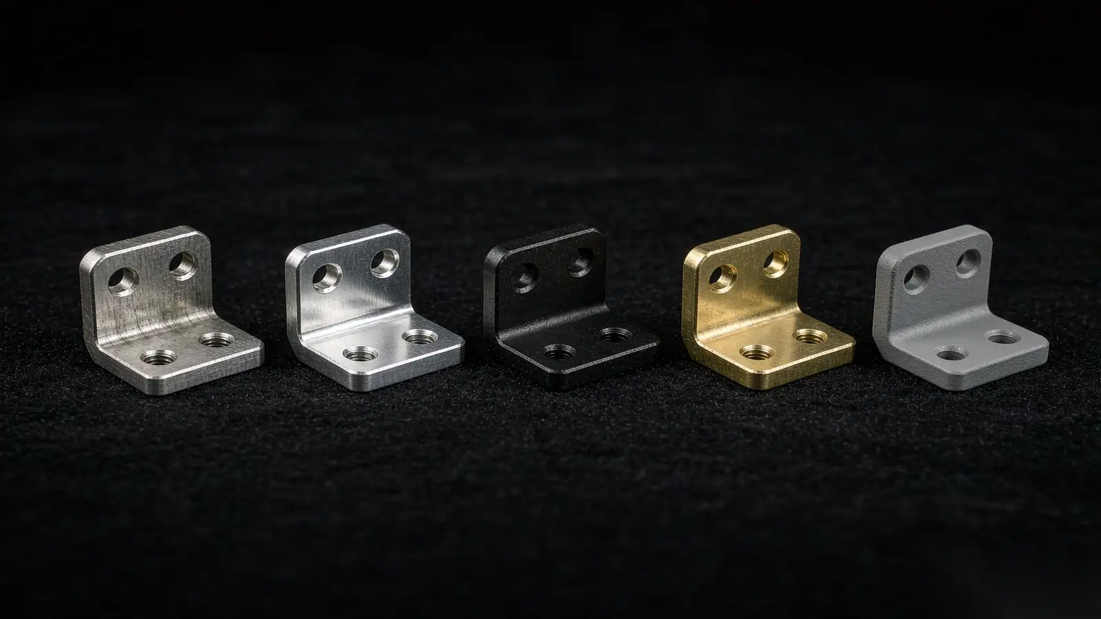
The final manufacturing cost reflects more than the cutting time required to produce the bracket's main shape. Surface treatments, edge requirements, marking, special tools, and inspection specifications may all contribute to the overall process.
6.1 Surface Treatments and Dimensional Allowances
Anodizing is a common finishing option for suitable aluminum alloys, while steel brackets may require protective coatings depending on the environment and specification. Treatments should be selected for their functional purpose, including corrosion protection, appearance, and surface durability.
The Aluminum Anodizers Council explains that the oxide formed during anodizing is “thicker than the aluminum that is consumed.” Consequently, anodizing can change finished dimensions, including the effective diameter of holes.
For close-fitting mounting features, the coating process and dimensional allowances should be considered before the drawing is finalized. Threaded areas or other critical interfaces may require masking or agreed post-treatment requirements.
Edge finishing and part identification also deserve attention. Functional chamfers and radii should be clearly defined, while marking requirements can be assessed according to visibility, durability, and traceability needs.
6.2 Design Features That Influence Manufacturing Cost
The table below summarizes common geometric choices that affect manufacturing effort. These are design-review considerations rather than guaranteed cost-saving measures.
| Feature | Potential Manufacturing Difficulty | Design Consideration |
| Deep blind holes | Drilling time and chip evacuation | Match depth to joint or functional requirements |
| Narrow pockets | Small cutters and restricted access | Review pocket opening and depth |
| Very small internal radii | Additional corner finishing | Use functionally acceptable radii |
| Tall, slender walls | Deflection and vibration | Review support and wall proportions |
| Multiple feature directions | Additional setups or tool orientations | Examine access and mounting geometry |
| Overly tight tolerances | Additional machining or inspection | Prioritize functional dimensions |
| Special surface finishes | Extra processing and dimensional allowances | Specify where functionally required |
The effect of these decisions also depends on production quantity. A prototype may favor flexible fixtures and straightforward setups, while a repeated production order can justify more specialized tooling.
Cost evaluation should therefore consider the whole bracket, including its structural requirements and expected volume, rather than modifying individual features in isolation.
What Should Engineers Check Before Releasing an Automotive Bracket Design?
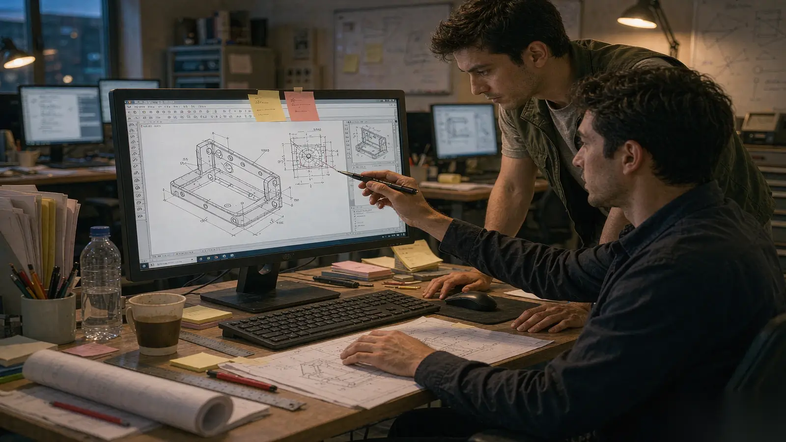
A final DFM review should confirm that the bracket can be manufactured using a practical machining strategy and that its drawing communicates the requirements needed for assembly and inspection.
| Design Area | Final Review Question |
| Application | Are mounting interfaces and structural requirements established? |
| Material | Does the selected grade meet mechanical and environmental requirements? |
| Machine access | Can critical features be reached by suitable cutting tools? |
| Holes and threads | Are hole depth, engagement, and fastener clearances adequate? |
| Pockets and radii | Are internal features compatible with practical cutter sizes? |
| Walls and ribs | Are slender sections properly supported and structurally validated? |
| GD&T | Are critical datums and tolerances clearly identified? |
| Surface finishing | Are coating effects on critical dimensions accounted for? |
| Drawing package | Are CAD files, drawings, quantities, and inspection requirements complete? |
A bracket combining deep pockets with closely positioned mounting features may benefit from an early manufacturing review, especially if the design is still open to adjustment. This review can distinguish geometry essential to the component's function from features that could be modified to improve machining access.
At SinoRise, such a review can focus on the customer's bracket drawing, including pocket accessibility, wall stability, and the relationship between mounting features and the planned milling approach. Resolving these questions before prototyping helps align the design with its manufacturing requirements.
Frequently Asked Questions
What is design for manufacturability in automotive bracket CNC milling?
Design for manufacturability is the process of reviewing a bracket's geometry, material, tolerances, and production requirements before machining. It identifies potential tool-access, workholding, and feature-design difficulties while keeping the component's structural and assembly functions intact.
Is 3-axis or 5-axis CNC milling better for automotive brackets?
Three-axis milling is suitable for many brackets with accessible planar features. Multi-axis machining may offer advantages when angled faces or restricted features require additional tool orientations. The preferred method depends on part geometry, setup requirements, and production volume.
What is the minimum wall thickness for an aluminum CNC bracket?
No universal minimum applies. Wall thickness depends on the selected alloy, unsupported height, loading, and required tolerances. Structural validation and a manufacturing review should be used to establish a suitable value.
Why are small internal corner radii more difficult to CNC mill?
Smaller internal radii generally require smaller end mills, which may reduce tool rigidity and cutting efficiency in deep pockets. Larger permissible radii can make machining more straightforward, provided the revised geometry satisfies structural and assembly requirements.
Does anodizing affect the dimensions of CNC machined aluminum brackets?
Yes. Anodizing forms an oxide layer that changes surface dimensions. The effect is particularly relevant to close-fitting holes, threads, and other critical interfaces, where coating allowances may need to be considered during design.
Conclusion
Good CNC milling design considers how a bracket's functional requirements translate into manufacturable geometry. Material choice, mounting holes, internal pockets, wall proportions, and finishing specifications can all influence machining difficulty and cost.
By reviewing these features together before drawing release, engineers can preserve the required structural and assembly performance while reducing avoidable manufacturing constraints.
Technical References
ASME Y14.5 – Dimensioning and Tolerancing — Functional GD&T, datum references, and drawing interpretation.
Sandvik Coromant – Milling Application Guide — Cutting-tool length, workpiece support, vibration, and machining stability.
Aluminum Anodizers Council – Anodizing FAQ — Anodizing-related dimensional changes and coating considerations.